Injection molding method

A technology of injection molding and molding materials, applied in the field of injection molding, which can solve the problems of difficulty in stably preparing molded products with uniform quality and uniform kneading, and achieve the effect of reducing the amount of feed and high quality

Inactive Publication Date: 2011-09-21
FUJIFILM CORP
View PDF2 Cites 13 Cited by
  • Summary
  • Abstract
  • Description
  • Claims
  • Application Information

AI Technical Summary

Problems solved by technology

In particular, when the powder ratio of the molding material exceeds 30% by weight, uniform kneading cannot be performed by conventional injection molding methods
[0014] The second problem is that, even if, for example, the powder material and the granular material once mixed by a mixer or the like for directly feeding the powder material and the granular material are fed into the hopper, the powder material and the granular material are caused by vibration of the injection molding equipment or The difference between the shape or specific gravity of the material separates during repeated injection molding
Thus, the ratio between the powder material and the granular material fed from the hopper into the barrel is not as designed, which makes it difficult to stably prepare molded products with uniform quality

Method used


Image

  • Injection molding method
  • Injection molding method
  • Injection molding method

Examples


no. 1 approach

[0082] A first embodiment of the subject matter of the present disclosure is an invention relating to metering time control in an injection molding process.

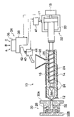
[0083] figure 1 is a schematic configuration diagram of one example of an injection molding apparatus that performs the injection molding method of the subject matter of the present disclosure.

[0084] as in figure 1 As shown in , the injection molding apparatus 10 includes a barrel 14 having a nozzle 12 at the tip, and a screw 16 is rotatably disposed in the barrel 14 . At the end opposite the nozzle 12 and at the rear end of the screw 16, there is located an electric motor / piston arrangement 22 comprising an electric motor 18 rotating the screw 16 and a piston arrangement 20 at a set point based on pressure and speed. The constant stroke (stroke) in the axial direction ( figure 1 In the transverse direction) the screw rod 16 is advanced and reversed. The piston device 20 causes the screw to figure 1 Push to the l...

no. 2 approach

[0133] A second embodiment of the disclosed subject matter relates to simultaneous feeding in an injection molding process.

[0134] The simultaneous feeding in the subject matter of the present disclosure can be performed so that the molding material containing at least the powder material and the granular material among the powder material, the granular material and the liquid material is directly fed into the barrel via the hopper 26 of the injection molding apparatus 10 In the case of injection molding in 14, it also prevents clogging and kneads the molding material in the barrel 14 uniformly.

[0135] It goes without saying, however, that synchronous feeding is combined with the "dosing time control" described above to further provide the advantages of synchronous feeding.

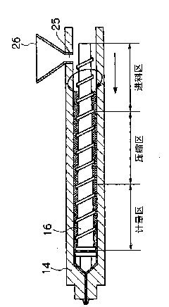
[0136] Figure 8 is a schematic configuration diagram showing an example of injection molding equipment that can perform simultaneous feeding. The basic structure of injection molding equipment 10 a...

Embodiment 1

[0237] In Example 1, a small metering feeder was installed to the injection molding equipment, the molding material having the above composition was placed in a plastic bag, shaken well and uniformly mixed, and then placed in the metering feeder. Set back pressure to 30kg / cm 2 , the rotation speed of the screw was set to 200 rpm, and the molding material was fed into the barrel at a feed speed at which the metering time was 20 seconds. Specifically, in Example 1, the feed rate of the molding material fed into the barrel was adjusted regardless of the rotation speed of the screw and the set value of the back pressure, thus controlling the metering time in the metering step to 20 seconds. As a result, the uniform kneading of the granular material and the powder material was fully performed, and the result of the Charpy impact test was 7.1 (KJ / cm 2 ), the flame retardancy was V-0, the dispersibility was A, and it was judged to be acceptable. Figure 11A is a photograph showing ...


PUM

PropertyMeasurementUnit
melting pointaaaaaaaaaa
impact strengthaaaaaaaaaa
lengthaaaaaaaaaa

Abstract

An injection molding method including a measuring step for measuring an amount of the molding material by storing a molding material fed into a cylinder of an injection molding apparatus in a tip of the cylinder by rotation of a screw and stopping a rotation of the screw after the screw is retracted to a measurement set position by a pressure from the stored molding material itself. The measuring step comprises: setting a back pressure to be applied on the screw, to a predetermined value; setting a rotation speed of the screw to a constant rotation speed within a predetermined range; and adjusting a feeding speed of the molding material to a predetermined time so that the measuring time is controlled irrespective of the rotation speed of the screw and the back pressure set value.

Description

technical field [0001] The subject matter of the present disclosure relates to an injection molding method, and more particularly, to an injection molding method in which a molding material containing a large amount of powder is directly fed from a hopper into a barrel. Background technique [0002] A typical resin (plastic) molding method is an injection molding method. The injection molding method is a method of filling a resin molding material molten in a heating cylinder (also simply called a cylinder) into a cavity portion of a mold including a male mold and a female mold using a screw or a plunger, and Rapid cooling and removal of the material from the mold to form a shaped product. [0003] The injection molding cycle usually includes a metering step, a mold clamping step, an injection step, a pressure holding step, a cooling step and a demoulding step. [0004] The metering step is now described in detail. In the metering step, the molding material fed into the ba...

Claims


Application Information

Patent Timeline
Patent Type & Authority Applications(China)
IPC IPC(8): B29C45/18
CPCB29C45/76B29C45/00B29B7/603B29B7/728B29B7/90B29C2945/76498B29C2945/76561B29C2945/76605B29C2945/76662B29C2945/76665B29C2945/76765B29C2945/76832
Inventor 小仓彻河崎英敏柳下博一
Owner FUJIFILM CORP
Why Eureka
Try Eureka