Bearing system for a wind turbine rotor

A technology of wind turbines and bearings, applied in the field of roller bearings, to achieve high life, improve fatigue life and usability, and avoid slippage

Inactive Publication Date: 2011-09-21
SIEMENS AG
View PDF0 Cites 4 Cited by
  • Summary
  • Abstract
  • Description
  • Claims
  • Application Information

AI Technical Summary

Problems solved by technology

Too high a bearing clearance will cause unacceptably high edge pressure on the rollers in a non-preloaded system

Method used


Image

  • Bearing system for a wind turbine rotor
  • Bearing system for a wind turbine rotor
  • Bearing system for a wind turbine rotor

Examples


Embodiment Construction

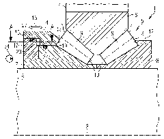
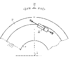
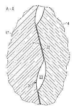
[0016] Such as Figure 1 to Figure 3 As shown, a wind turbine rotor comprises a bearing system 1 , a wind turbine shaft 2 with an axis 3 and a rotor hub 4 , wherein the shaft 2 is fixed and the rotor hub 3 is rotating. A rotor blade or a plurality of rotor blades (not shown) are mounted on the rotor hub 4 and extend in radial direction. The rotor hub 4 is supported to the rotor shaft 2 by the bearing system 1 such that the rotor hub 4 is pivotally mounted on the wind turbine shaft 2 . The bearing system 1 sustains radial forces, axial forces and tipping moments caused by wind loads, the weight of the blades and the rotor hub 4 and unbalance of the wind turbine rotor, etc. In order to provide a stable structure for a wind turbine rotor capable of withstanding operational loads, the bearing system 1 comprises double row tapered roller bearings 5 ​​in an O-arrangement. The double-row tapered roller bearing 5 includes a split collar consisting of a first inner ring 7 and a secon...


PUM


Abstract

A bearing system for a wind turbine rotor comprises a double row tapered roller bearing (5) in O-arrangement, wherein the double row tapered roller bearing (5) comprises an inner ring (7), a circumferential row of tapered rollers (9) supported on the inner ring (7), and a floating inner rib (14), a driving device (26) as well as an removable interlocking device (17 - 24), wherein the floating inner rib (14) can be axially moved by the driving device (26) to a predetermined position so as to abut on each large roller end (11) facing axially outwards in order to apply a corresponding preload on each tapered roller (9), and rigidly coupled to the inner ring (7) by means of the interlocking device (17 - 24).

Description

technical field [0001] The invention belongs to the technical field of roller bearings and relates to a bearing system for a wind turbine rotor. Background technique [0002] In wind turbine applications, large main bearings with higher operating clearances have lower rating life than bearings without clearances or bearings with optimum minimum preload. In particular, non-preloaded double row bearings in an O- or X-arrangement have lower stiffness. When these bearings are loaded with high radial forces or high tipping moments, the load distribution on the rolling elements becomes irregular. As a result, some rolling elements are subjected to high Hertzian stresses, causing premature bearing failure. In particular, the bearing stiffness depends on the preload and the load resulting from the current operating state of said bearing. Double row bearings with an excessively high preload have higher stiffness and therefore higher friction in the bearing. As a result, internal ...

Claims


Application Information

Patent Timeline
Patent Type & Authority Applications(China)
IPC IPC(8): F03D11/00
CPCF16C33/605F16C2300/14F05B2240/50Y02E10/722Y02E10/72F16C19/386F03D11/0008F16C35/063F16C25/08F03D80/70F16C2360/31
Inventor K.文茨克
Owner SIEMENS AG
Why Eureka
Try Eureka