Infrared zooming lens

A zoom lens and infrared technology, applied in the field of infrared zoom lens, can solve the problems of low refractive index of zinc sulfide, difficult aberration correction, large infrared absorption, etc., and achieve easy field curvature and astigmatism, light weight, and less infrared absorption. Effect

Active Publication Date: 2011-09-21
TAMRON
View PDF7 Cites 18 Cited by
  • Summary
  • Abstract
  • Description
  • Claims
  • Application Information

AI Technical Summary

Problems solved by technology

Zinc sulfide has problems with low refractive index (about 2.2), difficulty in correcting aberrations, and absorption of infrared rays greater than that of Ge
[0016] In the structure of Patent Document 3, since 9 to 12 lenses are used, not only the manufacturing cost is high, but also the lens itself absorbs a lot of infrared rays, causing the image to become darker.
In addition, there are problems that the lens barrel becomes larger and the structure becomes more complicated.

Method used


Image

  • Infrared zooming lens
  • Infrared zooming lens
  • Infrared zooming lens

Examples


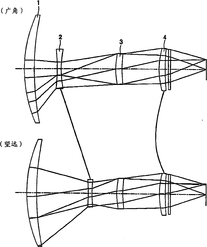
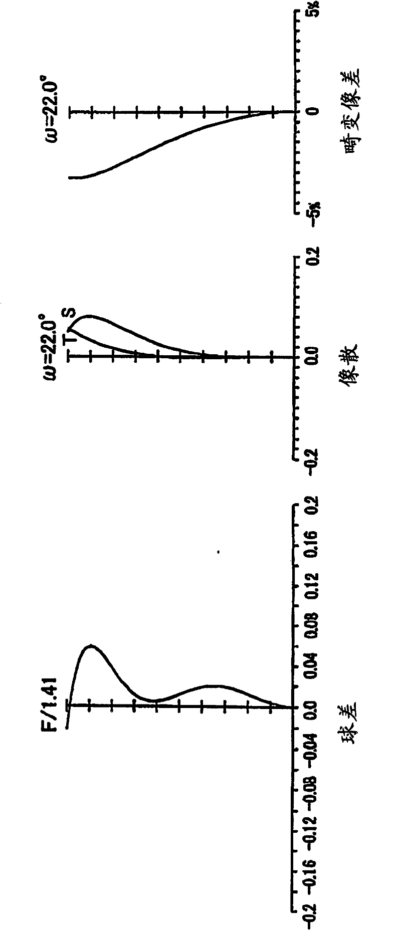
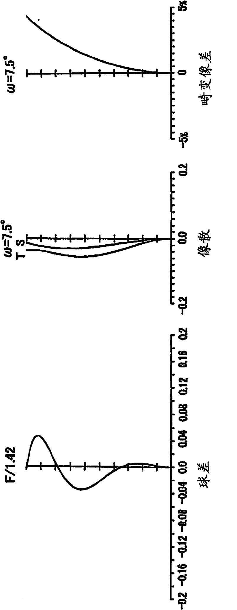
no. 1 Embodiment approach

[0084] The lens data and the like of the first embodiment are listed below.

[0085]

[0086] The part where the lens distance changes with the change of the focal length is represented by D(i).

[0087] The surface with the ASPH symbol after the lens surface serial number is an aspheric surface. The expression of the aspheric surface shape is expressed by the following formula, where the height perpendicular to the optical axis is H, the displacement of the height H in the direction of the optical axis when the top of the lens surface is taken as the origin is X(H), and the paraxial curvature The radius is R, the cone coefficient is ε, the 2nd aspheric coefficient is A, the 4th aspheric coefficient is B, the 6th aspheric coefficient is C, the 8th aspheric coefficient is D, and the 10th aspheric coefficient is E.

[0088] X = H 2 / R 1 ...

no. 2 Embodiment approach

[0094] Lens data and the like of the second embodiment are listed below.

[0095]

[0096] Aspheric Data

[0097]

[0098] Lens Group Interval for Zoom Action

[0099]

no. 3 Embodiment approach

[0101] Lens data and the like of the third embodiment are listed below.

[0102]

[0103] Aspheric Data

[0104]

[0105] Lens Group Interval for Zoom Action

[0106]


PUM


Abstract

The present invention is directed to an infrared zoom lens that consists merely of optical components of germanium so as to implement an optical system that is capable of reducing variation in brightness during varying a magnification rate and is quite bright and that facilitates compensating for aberration, especially spherical aberration that is generally hard to do, thereby producing a clear and vivid image. The infrared zoom lens comprises first to fourth groups of lens pieces arranged in series from the foremost position closest to the object; each of the lens groups having all the lens pieces made of germanium, and at least one of the lens groups consisting simply of a single lens piece.

Description

technical field [0001] The invention relates to an infrared zoom lens with excellent spherical aberration correction and low manufacturing cost. Background technique [0002] As a conventional infrared zoom lens, there is proposed an adiabatic infrared zoom lens, which is composed of a lens element having a first lens element arranged in order along the optical axis from the direction of the object to the focus direction, The 2nd lens element, the 3rd lens element; The 1st lens element has the 1st surface and the 2nd surface that is positioned at the opposite side of above-mentioned 1st surface, and the 1st lens element has positive magnification; The 2nd lens element has the 1st surface surface and a second surface on the opposite side of the first surface, and the second lens element has a negative power; the third lens element has a first surface and a second surface on the opposite side of the first surface, and The third lens element has a positive power; the first and...

Claims


Application Information

Patent Timeline
Patent Type & Authority Applications(China)
IPC IPC(8): G02B15/16G02B13/18H04N5/225
CPCG02B13/008G02B13/14G02B9/34G02B15/14G02B13/18G02B15/144113
Inventor 安藤稔
Owner TAMRON
Why Eureka
Try Eureka