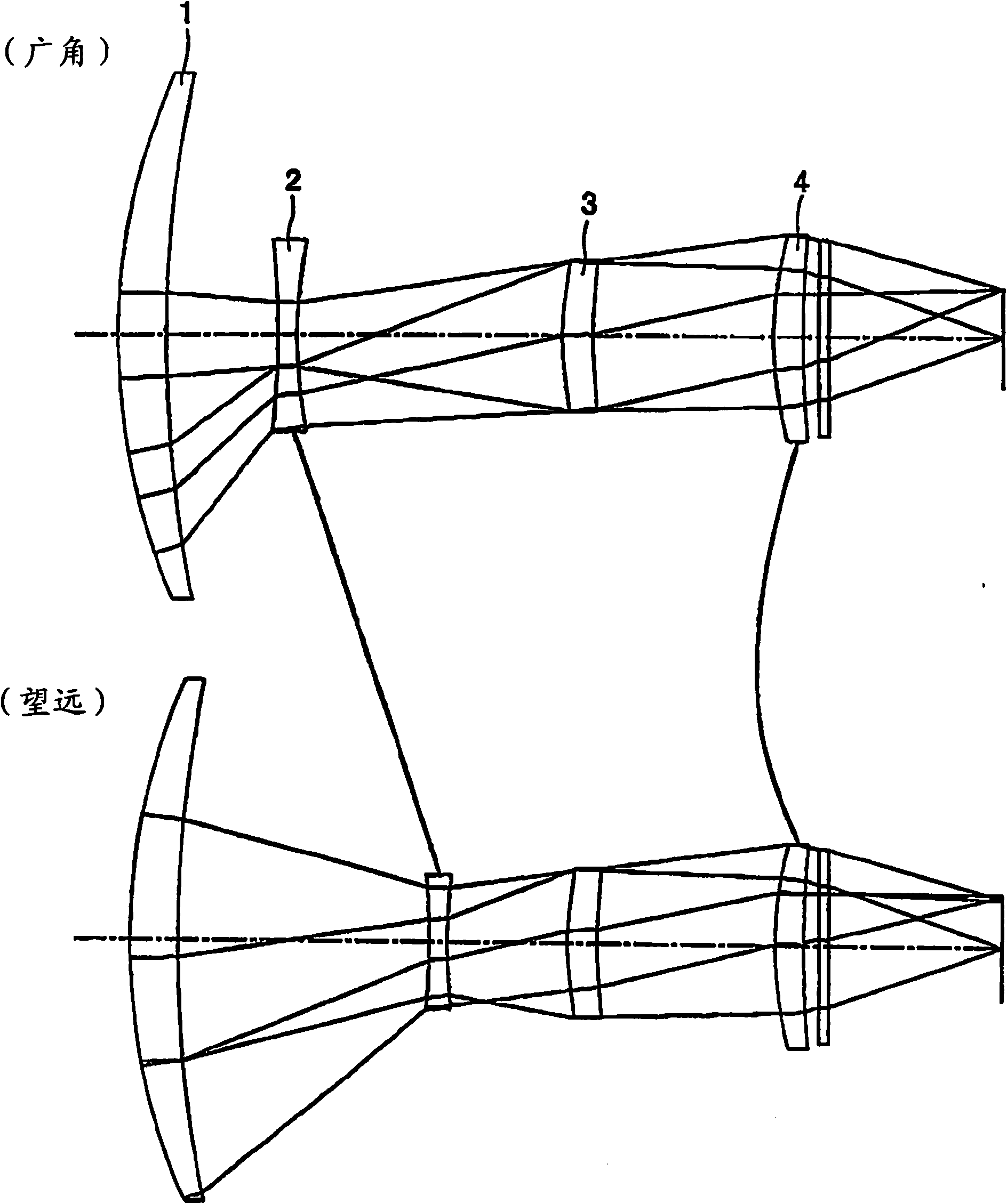
Infrared zooming lens
一种变焦镜头、红外线的技术,应用在红外线变焦镜头领域,能够解决硫化锌折射率低、像差校正困难、红外线吸收大等问题,达到容易场曲及像散、重量轻、吸收红外线少的效果
- Summary
- Abstract
- Description
- Claims
- Application Information
AI Technical Summary
Problems solved by technology
Method used
Image

Examples
no. 1 Embodiment approach
[0084] The lens data and the like of the first embodiment are listed below.
[0085]
[0086] The part where the lens distance changes with the change of the focal length is represented by D(i).
[0087] The surface with the ASPH symbol after the lens surface serial number is an aspheric surface. The expression of the aspheric surface shape is expressed by the following formula, where the height perpendicular to the optical axis is H, the displacement of the height H in the direction of the optical axis when the top of the lens surface is taken as the origin is X(H), and the paraxial curvature The radius is R, the cone coefficient is ε, the 2nd aspheric coefficient is A, the 4th aspheric coefficient is B, the 6th aspheric coefficient is C, the 8th aspheric coefficient is D, and the 10th aspheric coefficient is E.
[0088] X = H 2 / R 1 ...
no. 2 Embodiment approach
[0094] Lens data and the like of the second embodiment are listed below.
[0095]
[0096] Aspheric data
[0097]
[0098] Lens Group Interval for Zoom Action
[0099]
no. 3 Embodiment approach
[0101] Lens data and the like of the third embodiment are listed below.
[0102]
[0103] Aspheric data
[0104]
[0105] Lens Group Interval for Zoom Action
[0106]
PUM
 Abstract
Description
Claims
Application Information