Joint debugging device and joint debugging method for workpiece table interferometer and mask table interferometer

An interferometer and mask stage technology, which is applied to exposure devices, measuring devices, optical devices, etc. in the photoengraving process, can solve the problems of difficult operation, large spacing, and complex lithography machine structure, and achieves flexible and easy use. Loading and unloading, small size effect

Active Publication Date: 2011-09-21
SHANGHAI MICRO ELECTRONICS EQUIP (GRP) CO LTD
View PDF3 Cites 4 Cited by
  • Summary
  • Abstract
  • Description
  • Claims
  • Application Information

AI Technical Summary

Problems solved by technology

In order to ensure the performance of the lithography machine, when installing the workpiece stage interferometer 13 and the mask stage interferometer 15, it is necessary to ensure that the horizontal beam 131 emitted by the workpiece stage interferometer 13 is parallel to the horizontal beam 151 emitted by the mask stage interferometer 15, but , the distance between the workpiece stage interferometer 13 and the mask stage interferometer 15 is relatively large, usually greater than 1000 mm, and the horizontal beam 131 emitted by the workpiece stage interferometer 13 and the horizontal beam 151 emitted by the mask stage interferometer 15 cannot be simultaneously intro

Method used


Image

  • Joint debugging device and joint debugging method for workpiece table interferometer and mask table interferometer
  • Joint debugging device and joint debugging method for workpiece table interferometer and mask table interferometer
  • Joint debugging device and joint debugging method for workpiece table interferometer and mask table interferometer

Examples


Example Embodiment

[0036] The following will combine Figure 2 ~ Figure 11 The joint debugging device and joint debugging method of the workpiece stage interferometer and the mask stage interferometer of the present invention will be further described in detail.

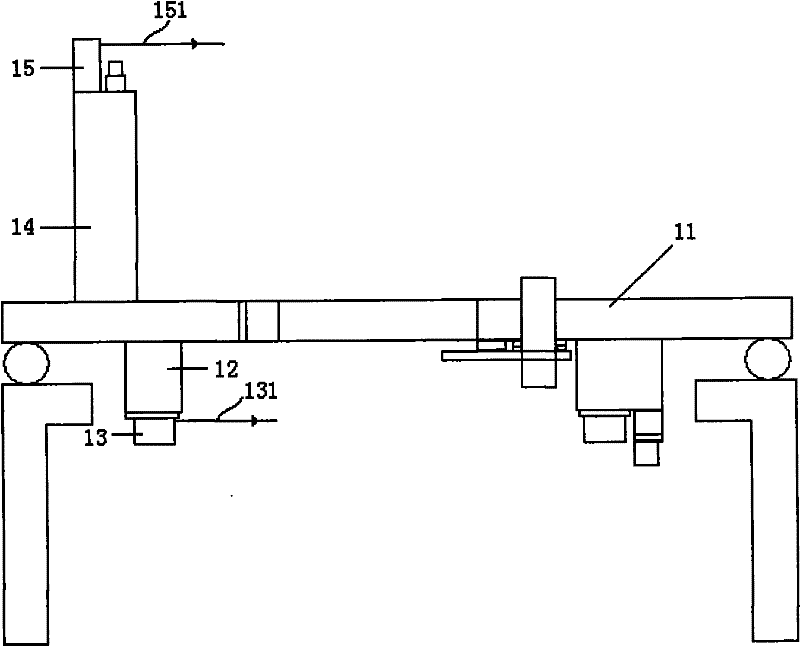
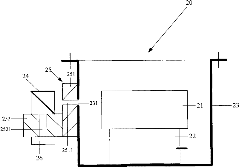
[0037] The joint debugging device of the workpiece stage interferometer and the mask stage interferometer of the present invention is used for online detection and adjustment of the workpiece stage interferometer and the mask stage interferometer, including multi-faceted mirror detection tooling, beam splitting prism group tooling and multi-faceted mirror reflection tooling ;

[0038] The multi-faceted mirror detection tool is used to adjust the workpiece table interferometer to lock the position of the workpiece table interferometer;

[0039] The dichroic prism group tooling is used to adjust the reflection tooling of the polygon mirror to lock the position of the reflection tool of the polygon mirror;

[0040] The dichroic prism gr...


PUM


Abstract

The invention relates to a joint debugging device and a joint debugging method for a workpiece table interferometer and a mask table interferometer. The joint debugging device is used for on-line detection and adjustment of the workpiece table interferometer and the mask table interferometer in a photo-etching machine. The joint debugging device comprises a multi-side reflector detection assembly, a light-splitting prism set assembly, and a multi-side reflector reflection assembly, wherein the multi-side reflector detection assembly is used for adjusting the workpiece table interferometer, thereby locking the position of the workpiece table interferometer; the light-splitting prism set assembly is used for adjusting the multi-side reflector reflection assembly, thereby locking the position of the multi-side reflector reflection assembly relative to the light-splitting prism set assembly; and the light-splitting prism set assembly and the multi-side reflector reflection assembly are jointly used for detecting the parallel degree of the emergent beam of the mask table interferometer and the emergent beam of the workpiece table interferometer, thereby locking the position of the masktable interferometer.

Description

technical field [0001] The invention relates to an interferometric measurement system of a lithography machine, in particular to a joint debugging device and a joint debugging method of a workpiece table interferometer and a mask table interferometer. Background technique [0002] In a lithography machine, the workpiece stage and the mask stage are each measured using a set of interferometric measurement systems. If the outgoing beam of the workpiece stage interferometer is not parallel to the outgoing beam of the mask stage interferometer, the alignment degree between the workpiece stage and the mask stage will be reduced, thereby affecting the performance of the lithography machine. Therefore, when installing the workpiece stage interferometer and the mask stage interferometer, it is necessary to ensure that the outgoing beam of the workpiece stage interferometer is parallel to the outgoing beam of the mask stage interferometer. [0003] like figure 1 As shown, in the li...

Claims


Application Information

Patent Timeline
IPC IPC(8): G03F7/20G01B11/27
Inventor 姜福君张志平
Owner SHANGHAI MICRO ELECTRONICS EQUIP (GRP) CO LTD
Why Eureka
Try Eureka