Switched capacitor amplifier circuit with clamping

A switched capacitor and clamp technology, which is applied in the field of switched capacitor amplifier circuit with clamp, can solve problems such as signal distortion

Active Publication Date: 2011-09-21
MAXIM INTEGRATED PROD INC
View PDF5 Cites 8 Cited by
  • Summary
  • Abstract
  • Description
  • Claims
  • Application Information

AI Technical Summary

Problems solved by technology

Some traditional switched capacitor amplifier circuits clamp a single input signal, but produce signal distortion in the effective operating range

Method used


Image

  • Switched capacitor amplifier circuit with clamping
  • Switched capacitor amplifier circuit with clamping
  • Switched capacitor amplifier circuit with clamping

Examples


Embodiment Construction

[0028] The following description is only to specifically illustrate representative embodiments of the present invention, and the application of the present invention is not limited to the methods disclosed in this application. For the sake of clarity, the same components in the drawings use the same symbols. The phrase "comprising at least one of A, B and C" means that in addition to the unit A or B or C, other units may be included. The steps described in the method of the present invention can be performed in a different order without changing the working principle of the present invention.

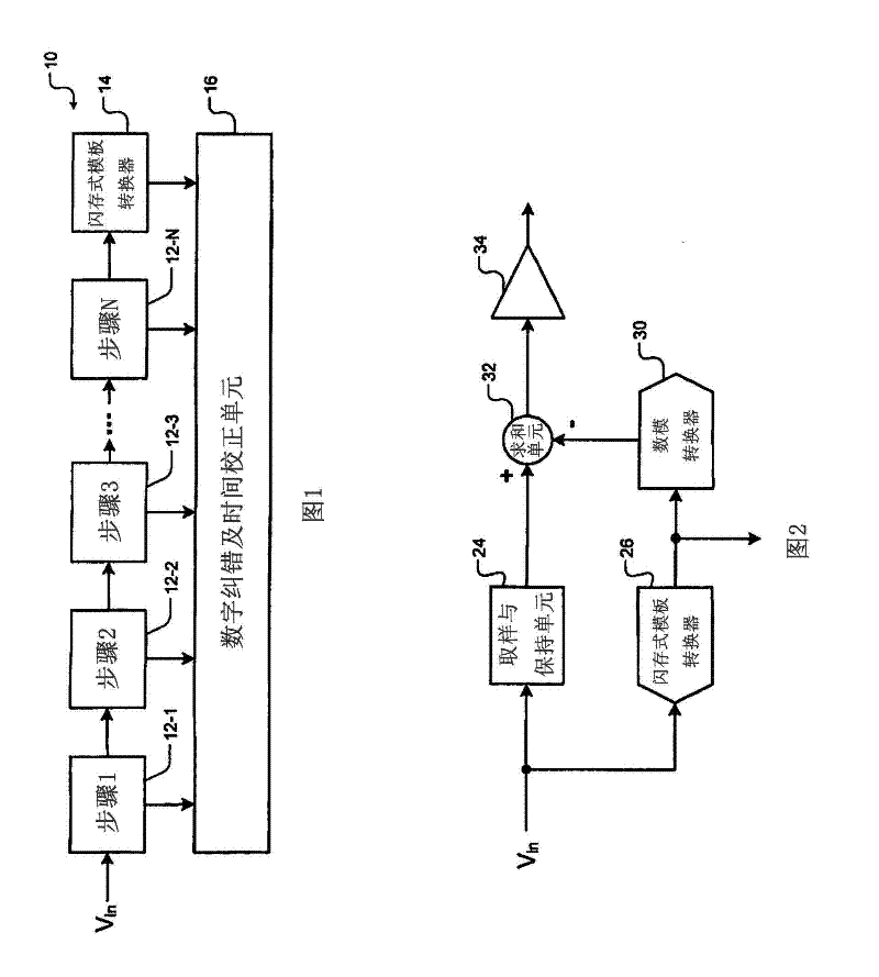
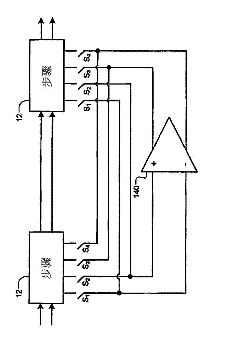
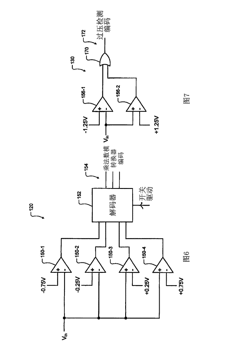
[0029] The clamping circuit of the present invention is used to improve the timely recovery when the signal exceeds the limit, even if the limit occurs frequently. The performance of the amplification system can be improved by quickly recovering from out-of-limit faults of the signal. The following describes the switched capacitor amplifying circuit with clamp and the multiplying digi...


PUM


Abstract

The invention discloses a switched capacitor amplifier circuit with clamping, comprising: a switched capacitor amplifier including an operational amplifier (opamp). A switching circuit comprises a first switch connected across inputs of the opamp. A second switch is connected across outputs of the opamp. An overdrive detect circuit communicates with the first and second switches and selectively shorts the inputs and the outputs of the opamp when the input voltage is greater than a first predetermined overdrive voltage or when the input voltage is less than a second predetermined overdrive voltage.

Description

technical field [0001] The invention relates to a switched capacitor amplifying circuit, in particular to a switched capacitor amplifying circuit with a clamp. Background technique [0002] The Background Art herein serves to generally present the context of the disclosure of the invention. [0003] Switched capacitor amplifier circuits are widely used. Switched capacitor amplifier circuits can experience gain errors when the signal is out of bounds. When the input signal of the operational amplifier in the switched capacitor amplifying circuit exceeds the limit, it takes multiple clock cycles to recover to an effective working state. During this intermediate transition time, the output signal often reports an error. Some conventional switched-capacitor amplifier circuits clamp a single input signal, but produce signal distortion in the effective operating range. Contents of the invention [0004] The technical problem to be solved by the present invention is to provi...

Claims


Application Information

Patent Timeline
Patent Type & Authority Applications(China)
IPC IPC(8): H03F3/45
CPCH03F3/005
Inventor 詹姆斯·E·贝尔斯
Owner MAXIM INTEGRATED PROD INC
Why Eureka
Try Eureka