Adaptive image repairing method

A repair method and adaptive technology, applied in the field of image repair, which can solve the problems of unsatisfied connectivity, long repair time, and inability to repair images correctly.

Inactive Publication Date: 2011-09-28
BEIJING PICOHOOD TECH
View PDF3 Cites 11 Cited by
  • Summary
  • Abstract
  • Description
  • Claims
  • Application Information

AI Technical Summary

Problems solved by technology

[0003] At present, image restoration generally adopts the Total Variation (TV) image restoration model (RUDIN L, OSHER S. FATEMI E. Nonlinear total variation based noise removal algorithms[J]. Physica D, 1992, 60(1~4) : 259-268.) and Curvature Driven Diffusion (CDD) image restoration model (CHAN T, SHEN J. Non-texture inpainting by curvature driven diffusions (CDD)[J]. Journal of Visual Communication and Image Representation, 2001, 12(4): 436-496.), among them, the TV image repair model adopts the TV image repair model although the repair time is less, but the biggest defect of the TV model is that it does not meet the "connectivity" principle in human vision, because The essence of the TV model is to connect the broken iso-illuminance lines. This is a straight-line connection. After calculating the extreme value, the connected straight line is required to be the shortest. Therefore, when the width of the repaired image is larger than the width of the image itself, The TV model cannot repair the image correctly; the CDD image repair model introduces the diffuse primer curvature k on the basis of the TV model, and the CDD model rises from the previous second-order partial differential to the third-order partial differential on the basis of the TV model, although it can repair damage Larger images, but the repair time is very long due to the calculation of the third-order partial differential for each point in a repair iterative operation

Method used


Image

  • Adaptive image repairing method
  • Adaptive image repairing method
  • Adaptive image repairing method

Examples


Embodiment 1

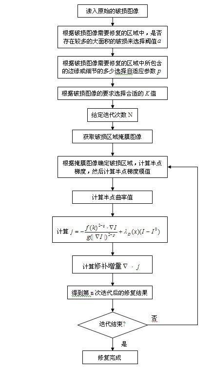
[0116] Example 1: Using the method of the present invention to perform image restoration on a Lena damaged image with scratches and special patterns, where the original image is shown in Figure 4(a), and the damaged image in Figure 4(a) is shown in Figure 4(b) , the mask image of Figure 4(b) is shown in Figure 4(c), and the inpainted image of Figure 4(b) is shown in Figure 4(d); when inpainting, set p =1.5, a =1.55, K =0.8, the number of iterations is 300, and the iteration step Take 1.

Embodiment 2

[0117] Example 2: Using the method of the present invention to repair the Lena damaged image with Chinese characters, where the original image is shown in Figure 5 (a), the damaged image of Figure 5 (a) is shown in Figure 5 (b), and Figure 5 ( The mask image of b) is shown in Figure 5(c), and the inpainted image of Figure 5(b) is shown in Figure 5(d); when inpainting, set p =0.35, a =0.8, K =0.9, the number of iterations is 300, and the iteration step Take 1.

[0118] To sum up, the adaptive image repair method of the present invention can adaptively use different image repair models for different images and in different damaged areas, and the image repair effect is good and the repair time is short.


PUM


Abstract

The invention provides an adaptive image repairing method. The method is characterized by comprising the following steps: A, reading a damaged image, and setting parameters according to the damaged image; A1, setting the threshold of a curvature adaptive coefficient according to the size of a fracture area of the damaged area of an image; A2, setting a gradient adaptive coefficient according to the edge or details in the image in the damaged area; A3, setting a constant according to the gradient range of the damaged image, required to be protected; and A4, setting iteration frequency and the step length of iterations; B, making a mask image for the damaged image, namely separating the damaged area of the image from the non-damaged area of the image; C, determining the position of the damaged area according to the mask image; D, calculating a semi-point gradient and a magnitude of the semi-point gradient of each point in the damaged area one by one; and E, calculating the semi-point curvature of each point of the damaged area one by one. The method has the advantages of good image repairing effect and short repairing time, and is suitable for automatically repairing all damaged images.

Description

technical field [0001] The invention relates to an image restoration method, in particular to an adaptive image restoration method. technical background [0002] In image processing, image restoration is an important basic research topic. Digital Image Inpainting is to automatically restore the lost or damaged information in the image according to the residual information in the image, so that the restored image is close to or achieves the visual effect of the original image. [0003] At present, image restoration generally adopts the Total Variation (TV) image restoration model (RUDIN L, OSHER S. FATEMI E. Nonlinear total variation based noise removal algorithms[J]. Physica D, 1992, 60(1~4) : 259-268.) and Curvature Driven Diffusion (CDD) image restoration model (CHAN T, SHEN J. Non-texture inpainting by curvature driven diffusions (CDD)[J]. Journal of Visual Communication and Image Representation, 2001, 12(4): 436-496.), among them, the TV image repair model adopts the T...

Claims


Application Information

Patent Timeline
Patent Type & Authority Applications(China)
IPC IPC(8): G06T5/00
Inventor 印勇李丁殷强胡琳昀
Owner BEIJING PICOHOOD TECH
Why Eureka
Try Eureka