Receiving device, signal processing device and image display

A receiving device and signal technology, applied in image communication, static indicators, cathode ray tube indicators, etc., can solve the problem of increasing the circuit scale of the receiving device, and achieve the reduction of area, cost and circuit scale Effect

Inactive Publication Date: 2011-09-28
PANASONIC CORP
View PDF11 Cites 5 Cited by
  • Summary
  • Abstract
  • Description
  • Claims
  • Application Information

AI Technical Summary

Problems solved by technology

However, depending on the number of corresponding communicatio

Method used


Image

  • Receiving device, signal processing device and image display
  • Receiving device, signal processing device and image display
  • Receiving device, signal processing device and image display

Examples


Example Embodiment

[0032] (Implementation)

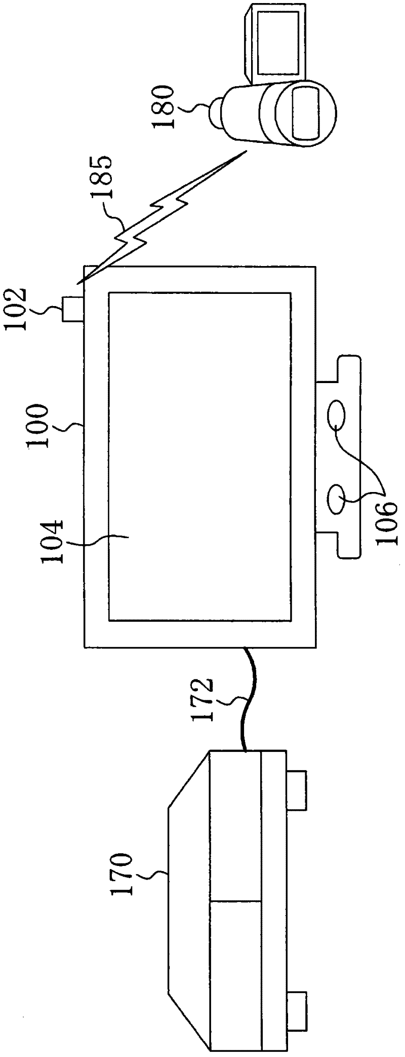
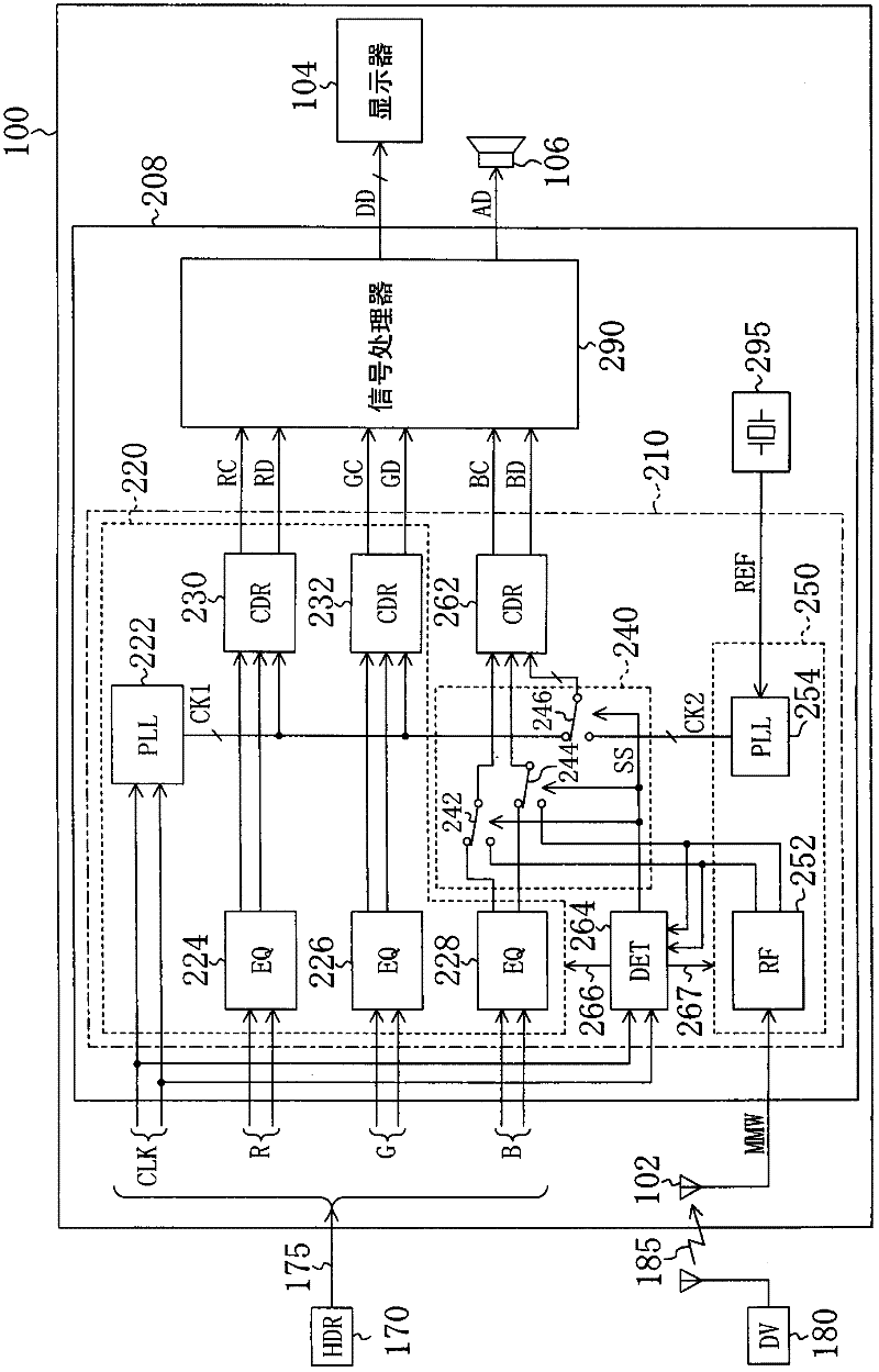
[0033] figure 1 It is a schematic diagram showing a video display device 100 according to an exemplary embodiment and a device that transmits a video to the video display device 100. The image display device 100 includes an antenna 102, a display 104, and a speaker 106 with an amplifier.

[0034] The reproduction device 170 outputs an HDMI signal for transmitting video and audio to the video display device 100 via the HDMI cable 172. The digital video camera 180 wirelessly transmits the UWB signal 185 that transmits video and sound to the video display device 100. The image display device 100 selects one of the two different communication methods of HDMI signal and UWB signal, and displays the image represented by the selected signal on the display 104.

[0035] The reproduction device 170 is any device that outputs at least one of a video signal and an audio signal. As an example, the reproduction device 170 may be HDR, Blu-ray Disc Player, DVD player, C...


PUM


Abstract

A circuit scale of a receiving device, which receives signals of a plurality of communication systems, is reduced. The receiving device, which receives base band signals and modulated signals, is provided with a first PLL circuit which generates a first internal clock based on an external clock synchronized with the base band signal; a demodulator which demodulates the modulated signal and outputs the demodulated signal; a selector which selects either the base band signal or the demodulated signal; and a first CDR circuit which generates a reproduction clock and reproduction data from the signal selected by the selector, by using the first internal clock.

Description

technical field [0001] The technology disclosed in this specification relates to a receiving device, and in particular, to a receiving device that receives signals of a plurality of communication methods. Background technique [0002] HDMI (High-Definition Multimedia Interface, High-Definition Multimedia Interface) is known as a communication method for transmitting high-definition video. HDMI is a wired communication system. For example, Patent Document 1 describes a technology for wirelessly transmitting HDMI signals. Non-Patent Document 1 describes a system in which high-definition video is transmitted without compressing it using radio waves in the 60 GHz band. In addition, the standard on millimeter wave wireless PAN (Personal Area Network, personal area network) is gradually formulated as IEEE802.15.3c. [0003] Patent Document 1: International Publication No. 2006 / 052339 [0004] Non-Patent Document 1: WirelessHD Specification Version 1.0 0 review, (USA), October 9...

Claims


Application Information

Patent Timeline
IPC IPC(8): H04N21/434H04N5/00H04N7/16
CPCG09G2370/22G09G2330/021H04N21/44G09G2370/20G09G2370/12G09G2370/16H04N7/163G09G5/006G09G2340/12H04N21/4305H04N21/43615
Inventor 山本明冈本好史白川佳则
Owner PANASONIC CORP
Why Eureka
Try Eureka