

Rotary motion and reciprocating motion converting device
A conversion device and reciprocating motion technology, applied in the direction of transmission device, friction transmission device, belt/chain/gear, etc., can solve the problems of reducing the working efficiency of the piston, increasing the resistance of starting and shifting, accelerating the wear of the cylinder wall, etc., to achieve power Reasonable conversion of transmission and motion mode, improvement of conversion efficiency, and effect of increasing tangential force
- Summary
- Abstract
- Description
- Claims
- Application Information
AI Technical Summary
Problems solved by technology
Method used
Image

Examples
Embodiment Construction
[0041] Specific embodiments of the present invention will be described in detail below with reference to the accompanying drawings.
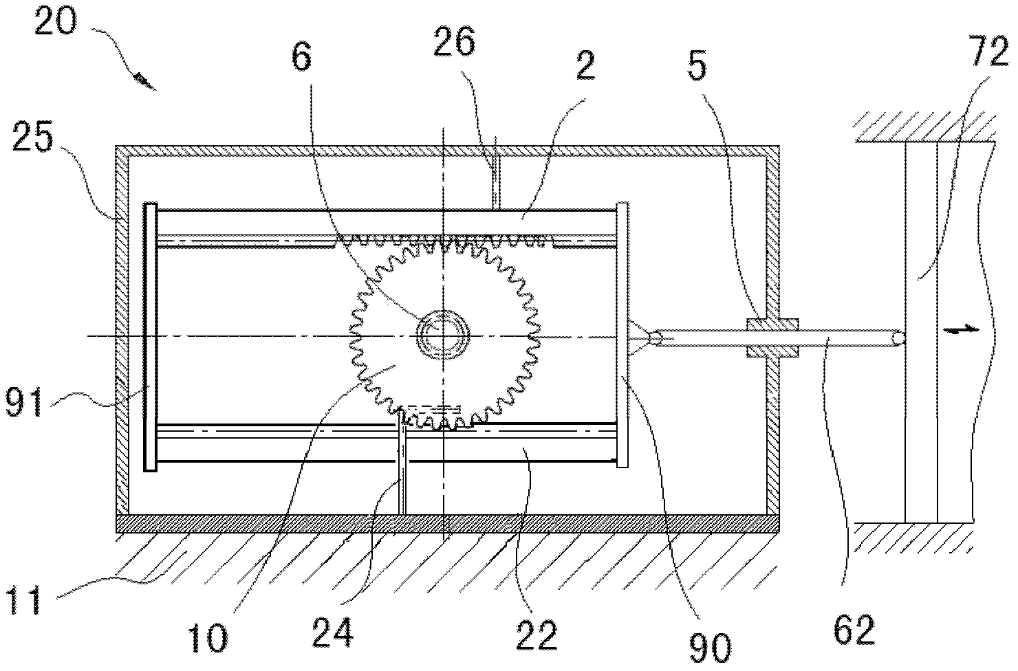
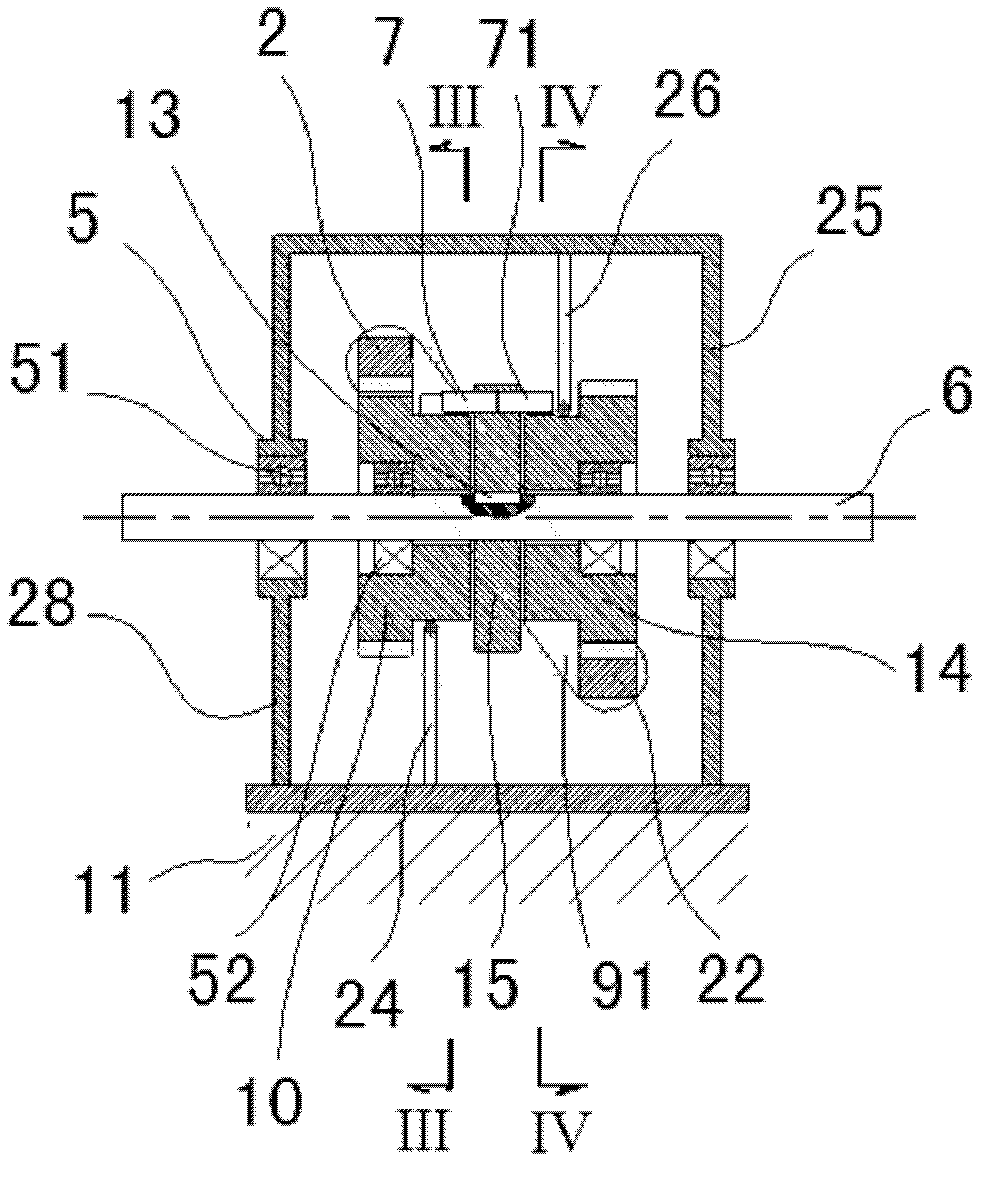
[0042] Such as Figure 1~4 As shown, a first embodiment provided by the present invention is depicted therein. exist figure 1 A rotary motion and reciprocating motion conversion device 20 provided by the present invention is depicted in , which includes a piston 72 , one end of the piston rod 62 is connected to the piston 72 , and the housing 25 is installed on the base 11 . The piston rod 62 passes through the end wall of the housing 25 and is connected to the connecting plate 90 . The connecting plate 90 is connected with the ends of the first rack 2 and the second rack 22 , and the first rack 2 and the second rack 22 are respectively located above and below the transmission shaft 6 .
[0043] Such as figure 2 As shown, a bearing seat 5 is provided on the side wall 28 of the housing 25 , the transmission shaft 6 is installed in the bearin...
PUM
 Abstract
Description
Claims
Application Information