Assembled center pillar inductor

A technology of inductors and side columns, applied in the field of inductors, can solve the problems of increasing production costs and circuit losses, reducing the service life of inductive devices, increasing copper resistance and copper loss, etc., to save copper, reduce power loss, and spread The effect of magnetic flux reduction

Active Publication Date: 2011-10-05
XIAMEN NANCI ELECTRONICS
View PDF8 Cites 4 Cited by
  • Summary
  • Abstract
  • Description
  • Claims
  • Application Information

AI Technical Summary

Problems solved by technology

The above reasons lead to an increase in the copper resistance and copper loss of the device itself, which increases the power consumption of the device, wastes electric energy and copper, and reduces the service life of the inductance device
In some electronic and electrical circuits, two or more inductors need to be used in series. The past practice is to use multiple independent inductors in series, which not only increases the area occupied by the inductor in the circuit, but also increases the production cost. and circuit losses

Method used


Image

  • Assembled center pillar inductor
  • Assembled center pillar inductor
  • Assembled center pillar inductor

Examples


Embodiment 1

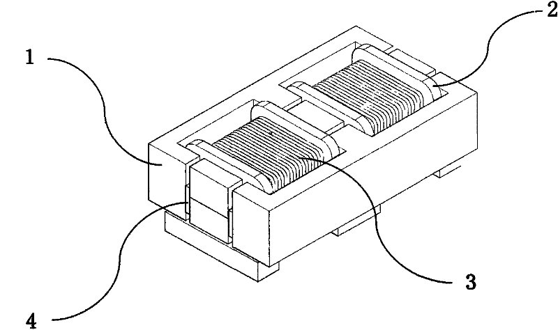
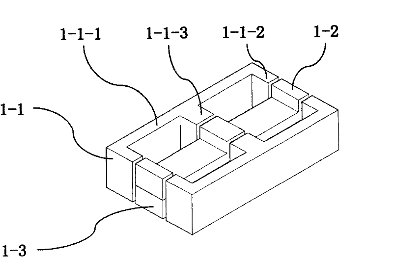
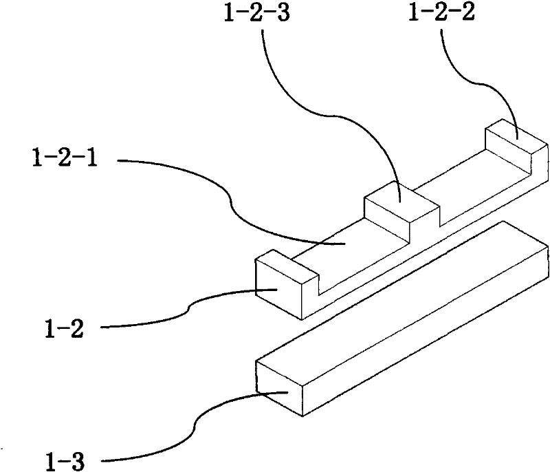
[0027] An embodiment of a combination center column inductor, see Figure 1 to Figure 4 , including a closed magnetic circuit magnetic core body 1, a skeleton 2 and a coil 3, the closed magnetic circuit magnetic core body is composed of a combined central column and two side column magnets 1-1; it is characterized in that the combined central column consists of a card The gear magnet 1-2 is composed of an I-shaped backing magnet 1-3; the clamping magnet is provided with a straight arm 1-2-1, and two end folding arms 1-2-2 are arranged at both ends of the straight arm , at least one middle folding arm 1-2-3 is arranged on the straight arm between the two end folding arms, and all the folding arms are located on the same side of the straight arm; the side column magnet 1-1 is provided with a folding arm; The skeleton is provided with at least two coil winding shafts 2-1, and a through space 2-6 is provided between two adjacent coil winding shafts. The hollow hole 2-4 is located ...

Embodiment 2

[0038] Another application embodiment of a combined central column inductor, see Embodiment 1. The difference from Embodiment 1 is that there is no air-gap medium slot on the edge of the hollow hole of the framework of this embodiment, and the edge is directly placed when assembling. The end face of the folded arm at the end of the column magnet is attached to the side surface of the combined central column, so that the air gap of the magnetic circuit is concentrated between the folded arm of the side column magnet and the side of the combined central column, so that the leakage flux of this embodiment can be reduced to Minimum value for best EMC performance.

Embodiment 3

[0040] Another application embodiment of a combined central column inductor, see Embodiment 1. The difference from Embodiment 1 is that the head end and tail end of the two coils are led out separately to form four circuit access points.

[0041] This embodiment can be used as a common-mode differential-mode integrated inductor in a circuit.


PUM


Abstract

The invention relates to an assembled center pillar inductor. The assembled center pillar inductor comprises a closed magnetic-loop magnetic core stack, a framework and windings, wherein the closed magnetic-loop magnetic core stack consists of an assembled center pillar and two side pillar magnets; the assembled center pillar consists of a clamping magnet and an I-shaped supporting magnet; a group of winding is coiled on each winding coiling shaft of the framework respectively; the coiling directions of two adjacent groups of windings are opposite; when the clamping magnet is arranged in a hollow hole of the framework and the supporting magnet is inserted into the hollow hole, a folding arm of the clamping magnet is clamped at both ends and the hollow part of the hollow hole; and the outward end faces of folding arms of the two side pillar magnets are attached to two side surfaces of the assembled center pillar so as to form at least two induction units. The assembled center pillar inductor has the advantages of effectively reducing the height of the winding framework, effectively enhancing an excitation angle of a magnetic loop and improving the structure of the magnetic loop.

Description

technical field [0001] The invention relates to an inductor, in particular to a combined central column inductor, which can be widely used in electronic circuits of various electronic appliances. Background technique [0002] Traditional inductance devices are generally composed of EE-type magnetic cores or EI-type magnetic cores with coil formers wound with enameled wires. In order to prevent the occurrence of magnetic saturation, the usual method is to use the method of grinding the core of the magnetic core to set the air gap of the magnetic circuit, and the air gap is located in the center of the coil of the inductor. Due to the diffuse magnetic flux near the air gap of the magnetic circuit, the diffuse magnetic flux makes the coil part near the air gap lose the "electric-magnetic" conversion effect, and the A of the magnetic core L When the value decreases, part of the coil near the air gap of the magnetic circuit only plays a role of filling. The larger the air gap, ...

Claims


Application Information

Patent Timeline
Patent Type & Authority Applications(China)
IPC IPC(8): H01F17/04H01F27/26H01F27/30
Inventor 黄思忠林金城陈限育徐晓辉
Owner XIAMEN NANCI ELECTRONICS
Why Eureka
Try Eureka