Welding structure with excellent resistance to brittle crack propagation

A brittle crack propagation and structure technology, applied in welding equipment, welding/welding/cutting items, arc welding equipment, etc., can solve problems such as prolonged process time, increased manufacturing cost, and reduced structural strength, and achieve high production efficiency , high security, the effect of inhibiting the spread

Inactive Publication Date: 2014-04-30
NIPPON STEEL CORP
View PDF4 Cites 0 Cited by
  • Summary
  • Abstract
  • Description
  • Claims
  • Application Information

AI Technical Summary

Problems solved by technology

However, in the welded structure of Patent Document 1, it is effective when the fracture toughness of the base material is very excellent, but when the fracture toughness of the base material is insufficient, brittle cracks deviated to the base metal side Longer propagation, as the strength of the structure may be significantly reduced
In addition, there are also problems in that the volume of the refilled welded part becomes larger, the process time is prolonged, and the manufacturing cost is also increased.
However, in the case where the welded structure described in Patent Document 2 is applied to a large building, for example, a brittle crack propagating in the welded joint propagates in the welded joint where the insert material is welded to the steel plate and enters into the insert. material, propagate as it is inside the inserted material, and then possibly again in the welded seam
On the other hand, when the brittle cracks propagating in the welded joint deviate toward the base metal side of the insert material and the welded joint position of the insert material welded to the steel plate, there is also a concern that there may be the following problem as above: When the fracture toughness of the material is not sufficient, brittle cracks propagate for a long time, and the strength as a welded structure is significantly reduced

Method used


Image

  • Welding structure with excellent resistance to brittle crack propagation
  • Welding structure with excellent resistance to brittle crack propagation
  • Welding structure with excellent resistance to brittle crack propagation

Examples


no. 1 Embodiment approach

[0061]

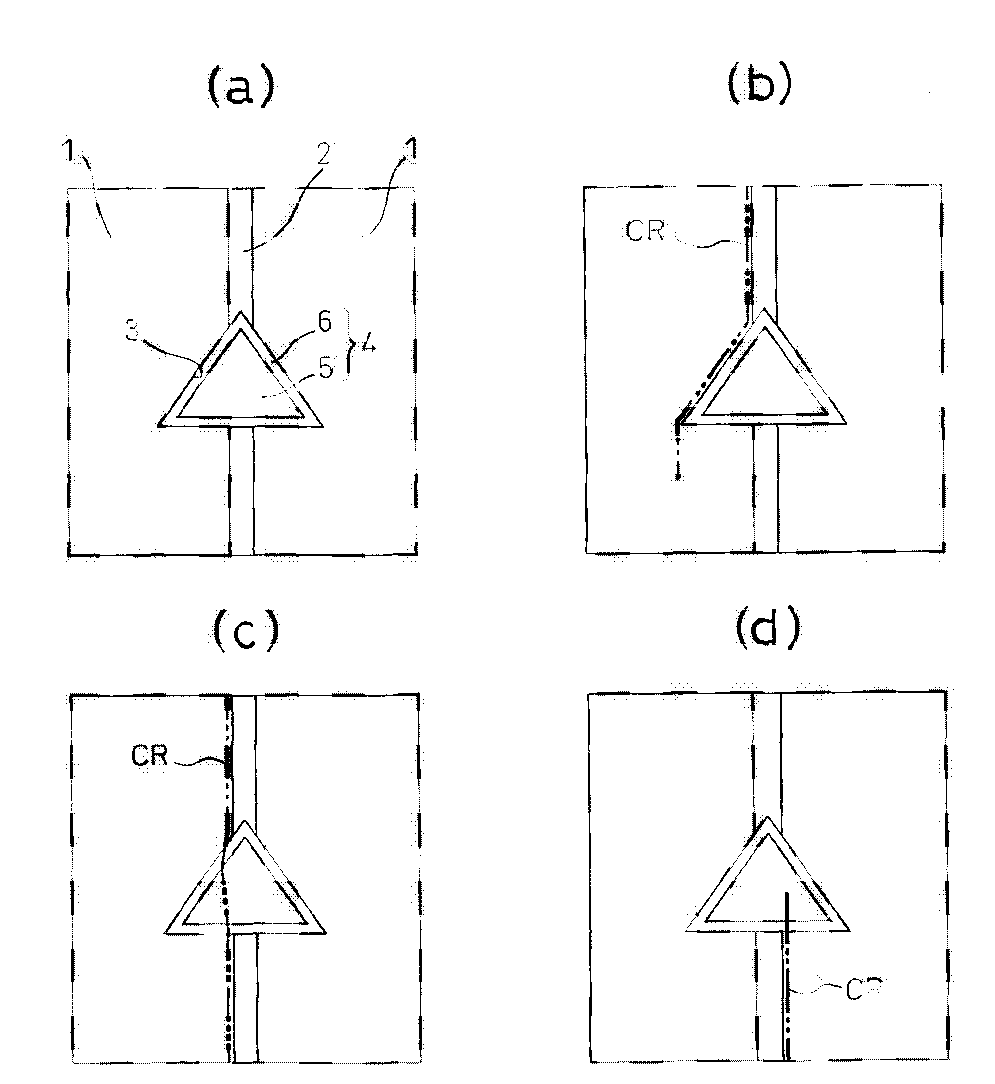
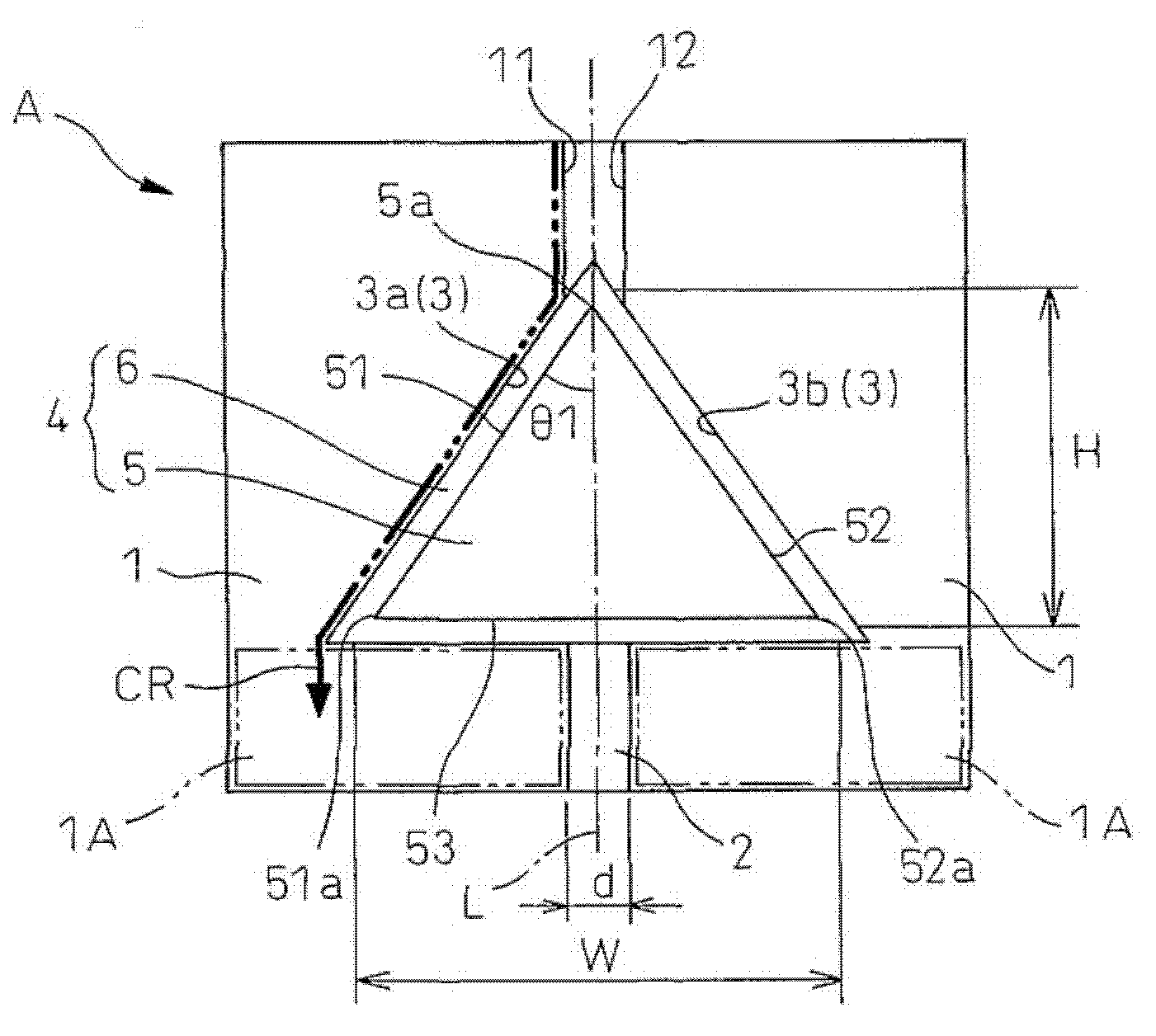
[0062] Such as figure 2 As shown, in the first embodiment, the brittle crack propagation arrest characteristic Kca of at least a part of the base material regions 1A and 1A is set to 4000 N / mm 1.5 An example of the case where the steel plates 1 and 1 are butt-welded to form the steel plate welded joint 2 will be described below by referring to the form applied to the joint as a welded structure A.

[0063] In the welded structure A, at least one portion of the steel plate welded joint 2 is provided with a crack resistance control portion 4 adjacent to the aforementioned region 1A. The position where the anti-crack control unit 4 is installed is preferably in the middle of a welded joint of steel plates where cracks are expected to occur and propagate when exposed to large destructive energy due to collisions, earthquakes, and the like.

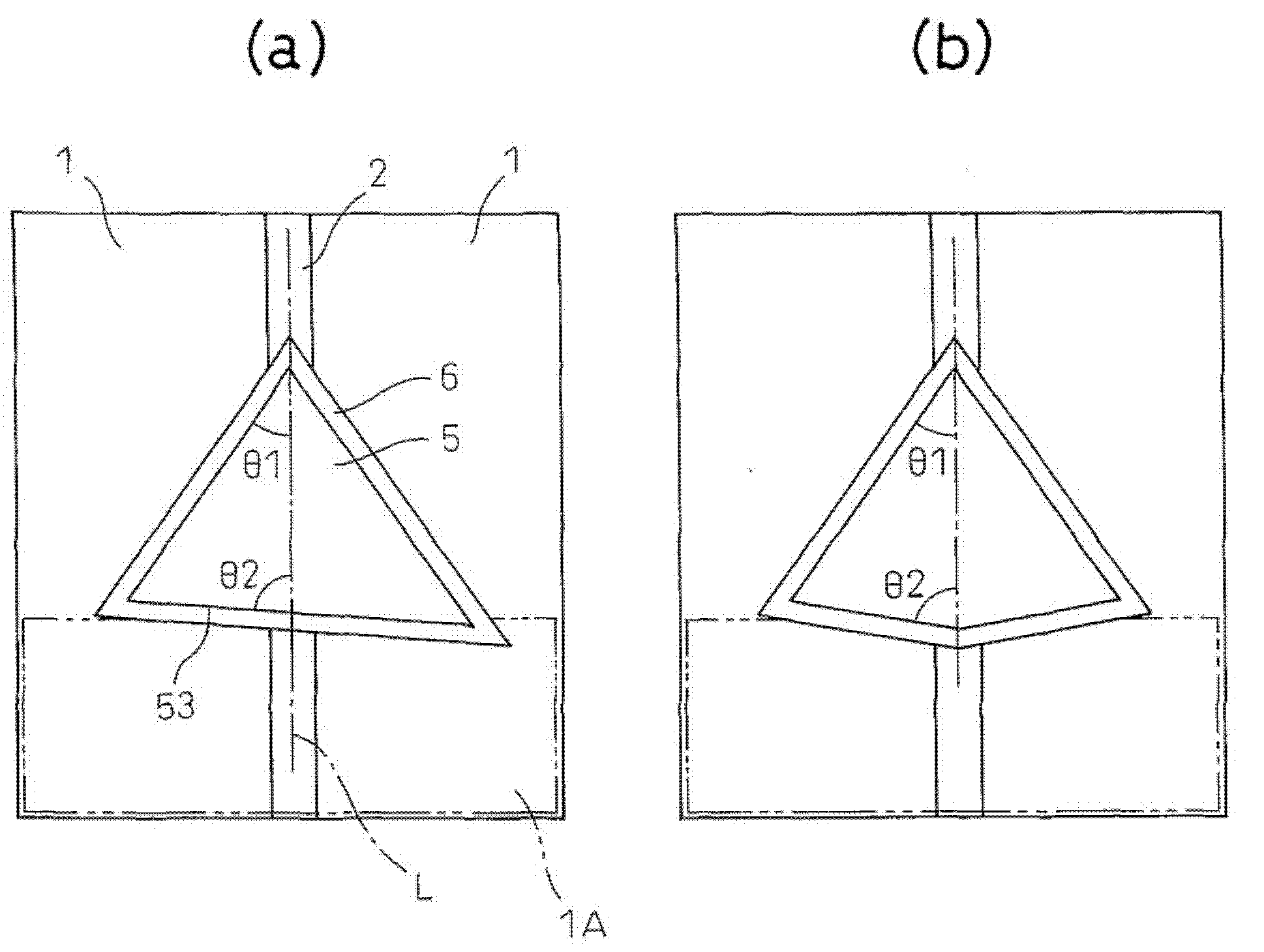
[0064] The crack resistance control part 4 is composed of an insertion member 5 disposed in the through-hole 3 provided to penet...

no. 2 Embodiment approach

[0135] Below, the main reference Figure 5 A welded structure B according to a second embodiment of the present invention will be described. In addition, in the following description, the same code|symbol is attached|subjected to the same structure as the welded structure A of the said 1st Embodiment, and detailed description is abbreviate|omitted. In addition, the same applies to the description of the third and fourth embodiments.

[0136] The welded structure B of the present embodiment is Figure 5 The detailed illustration is omitted in , but the brittle crack propagation stop characteristic Kca of the entire base material of the steel plate 10 is set to 4000N / mm 1.5 This point is different from the welded structure A of the first embodiment.

[0137] According to the welded structure B, when a brittle crack occurs in the steel plate welded joint 20, the crack propagating in the steel plate welded joint 20 can be made to extend along the boundary between the inserted w...

no. 3 Embodiment approach

[0141] The main reference below Image 6 A welded structure C according to a third embodiment of the present invention will be described in detail.

[0142] The welded structure C is a butt-welded steel plate and is an example in which a plurality of small steel plates are butt-welded.

[0143] That is, if Image 6 As shown, the steel plate 10A is at least two or more small steel plates arranged in the longitudinal direction of the steel plate welding joint 20A (refer to Image 6Symbols 21 to 24 in ) are formed by butt welding, and the crack resistance control part 4 is provided in the steel plate welded joint 20A formed by butt welding the steel plates 10A and 10A.

[0144] Small steel plate welded joints 25, 26 are formed between the small steel plates 21 to 24, and the insertion welded joint 6 formed on the side of the outer edge portion 53 of the secondary confrontation side of the insert member 5 is connected to the small steel plate welded joints 25, 26. contact setti...


PUM

PropertyMeasurementUnit
thicknessaaaaaaaaaa
thicknessaaaaaaaaaa

Abstract

A welded structure wherein steel plates having at least partial regions with a brittle crack arrest property Kca of 4000N / mm 1.5 or more are butt welded together so as to form a steel plate welded joint, wherein at least one location of the steel plate welded joint is provided with a crack control part which diverts a brittle crack which has occurred at the steel plate welded joint to a steel plate base metal side, outer edges of an insert member which forms the crack control part are formed to extend in the longitudinal direction of the steel plate welded joint from a weld metal zone of the steel plate welded joint while slanted by 15° to 50° with respect to the longitudinal direction of the steel plate welded joint, and a horizontal width direction end of the insert member is made to face a region of the steel plate where the Kca is 4000N / mm 1.5 or more, whereby even if a brittle crack occurs in the welded joint, the brittle crack can be kept from propagating through the weld joint and base metal.

Description

technical field [0001] The present invention relates to a welded structure excellent in brittle crack propagation resistance which controls and suppresses the propagation of brittle cracks when brittle cracks occur in welded joints. [0002] In particular, even when a brittle crack occurs in a welded joint of a welded structure welded by using a thick steel plate, the propagation of the brittle crack can be controlled and suppressed to improve safety, and the brittle crack propagation resistance is excellent. welded structure. Background technique [0003] In recent years, welded structures represented by welded structures for ships such as large container ships and bulk carriers, architectural structures, and civil engineering steel structures have been required to have high safety against damage such as brittle cracks. In particular, the increase in the size of container ships is very obvious. For example, large container ships of 6,000 TEU or more can be manufactured, an...

Claims


Application Information

Patent Timeline
Patent Type & Authority Patents(China)
IPC IPC(8): B23K31/00B23K9/23B23K103/04
CPCB23K2203/04B23K33/004B23K2201/18B23K9/0282B23K2201/12B23K9/0203B23K9/23B23K2101/12B23K2101/18B23K2103/04B23K31/00C22C38/58
Inventor 石川忠井上健裕桥场裕治大谷润
Owner NIPPON STEEL CORP
Why Eureka
Try Eureka