Vehicle communication control device

A technology for communication control and vehicle use, applied in control systems, DC motor speed/torque control, electric vehicles, etc., can solve problems such as difficulty in ensuring communication reliability, communication delay, inability to perform high-speed communication, and signal transmission

Active Publication Date: 2011-10-05
三电株式会社
View PDF3 Cites 9 Cited by
  • Summary
  • Abstract
  • Description
  • Claims
  • Application Information

AI Technical Summary

Problems solved by technology

[0003] In recent years, communication protocols such as CAN (Controller Area Network (Controller Area Network)) [in-vehicle LAN] have begun to be adopted with high communication speeds. Figure 5 In the existing structure shown (or as shown in Patent Document 1), the optical coupler 208 is directly used to connect the high-speed communication bus (CAN bus) 207 and the control microcomputer 209, but because there is no optical coupler for high-speed communication at present. coupler, therefore, there is a problem that a communication delay occurs due to a response delay of the photocoupler 208, making it difficult to ensure communication reliability
That is, the photocoupler 208 is not suitable for high-speed signals, so high-speed communication and signal transmission cannot be basically performed.

Method used


Image

  • Vehicle communication control device
  • Vehicle communication control device
  • Vehicle communication control device

Examples


Embodiment Construction

[0023] Hereinafter, preferred embodiments of the present invention will be described with reference to the drawings.

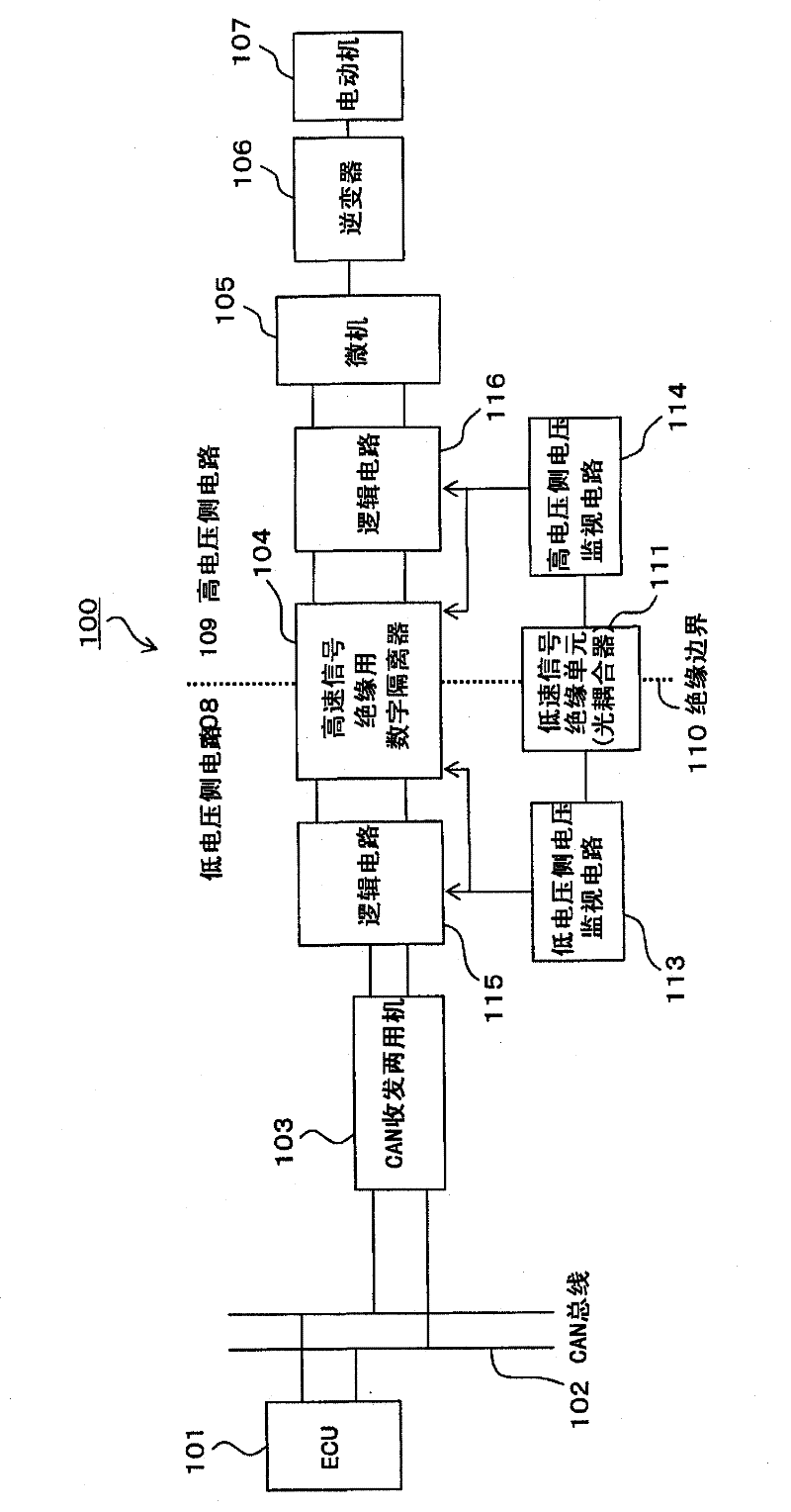
[0024] figure 1 An example of the basic structure of the vehicle communication control device according to the present invention is shown, particularly a case where an on-vehicle motor is controlled via an inverter having a switching element (power semiconductor element). exist figure 1 In the vehicle communication control device 100 shown, the control signal from the vehicle ECU 101 as the upper controller is received by the CAN transceiver 103 via the CAN bus 102, and the control signal passes through the high-speed signal isolation unit from there. A digital isolator 104 , a microcomputer 105 , and an inverter 106 are used for isolation of high-speed signals, and are transmitted to a motor 107 . The digital isolator 104 for high-speed signal isolation is installed on the insulation boundary 110 set between the low-voltage side circuit 108 and the high-v...


PUM


Abstract

Provided is a vehicle communication control device for which a signal isolation means-in particular, an isolation boundary equipped with a digital isolator-is configured between a high-voltage region and a low-voltage region, and which is capable of preventing erroneous output from the signal isolation means and of performing vehicle communications and microcomputer control correctly when the power supply voltage decreases due to, for example turning on of the power, or a power interrupt. Disclosed is a vehicle communication control device for which a signal isolation means-an isolation boundary equipped with a digital isolator-is configured between a microcomputer provided in a high-voltage region and a control signal transmission / reception means disposed in a low-voltage region, and which is characterized in that the signal isolation means is provided with a voltage monitoring means and an erroneous output prevention means that is capable of controlling or fixing the output, which is from the signal isolation means to the high-voltage side and / or the low-voltage side, to a safe output when the variation in the voltage detected by the voltage monitoring means by more than a prescribed amount.

Description

technical field [0001] The present invention relates to a communication control device for a vehicle, and particularly relates to the requirements for sending a control signal transmitted from a high-level controller to a low-voltage area by communication to a motion control device for an in-vehicle electric device via a microcomputer arranged in a high-voltage area. A vehicle communication control device that sets an insulating boundary between a low-voltage area and a high-voltage area. Background technique [0002] As an on-vehicle electric device, in order to control the drive of a motor of an electric compressor used in a vehicle air conditioner, for example, a technique is known in which a DC power supplied from a DC power supply (for example, a high-voltage power supply) is passed through a plurality of The switching elements and the inverter of the gate drive circuit convert quasi-AC power (for example, three-phase AC power) and apply the quasi-AC voltage to the moto...

Claims


Application Information

Patent Timeline
Patent Type & Authority Applications(China)
IPC IPC(8): B60R16/02B60R16/023H02M7/48H04L25/02
CPCY02T10/7241H04B10/802B60R16/023Y02T90/16H02P7/00
Inventor 黑崎桂
Owner 三电株式会社
Why Eureka
Try Eureka