
Clamp for coupling welding light-emitting device

A technology of light emitting devices and fixtures, applied in laser welding equipment, welding equipment, welding equipment, etc., can solve the problems of large changes in product indicators, poor consistency of new device performance, non-parallel, etc., to ensure the quality of coupling welding and improve work. Efficiency, effect of shortened time

Active Publication Date: 2011-10-12
SOURCE PHOTONICS CHENGDU
View PDF5 Cites 43 Cited by
  • Summary
  • Abstract
  • Description
  • Claims
  • Application Information

AI Technical Summary

Problems solved by technology

In this way, the coaxial positioning between the ferrule, the optical component base and the laser diode depends on the proficiency of the operator, and has the advantages of slow speed, low output, poor consistency of device performance, product cost and price. High disadvantages; at the same time, due to the differences in the processing accuracy of the ferrule, the base of the optical device component, and the laser diode, there are also non-parallel parts of the upper and lower workpiece veneers after clamping, resulting in large changes in product indicators before and after welding, low production pass rate, and low product quality. problems such as poor temperature performance

Method used


Image

  • Clamp for coupling welding light-emitting device
  • Clamp for coupling welding light-emitting device
  • Clamp for coupling welding light-emitting device

Examples


Embodiment Construction

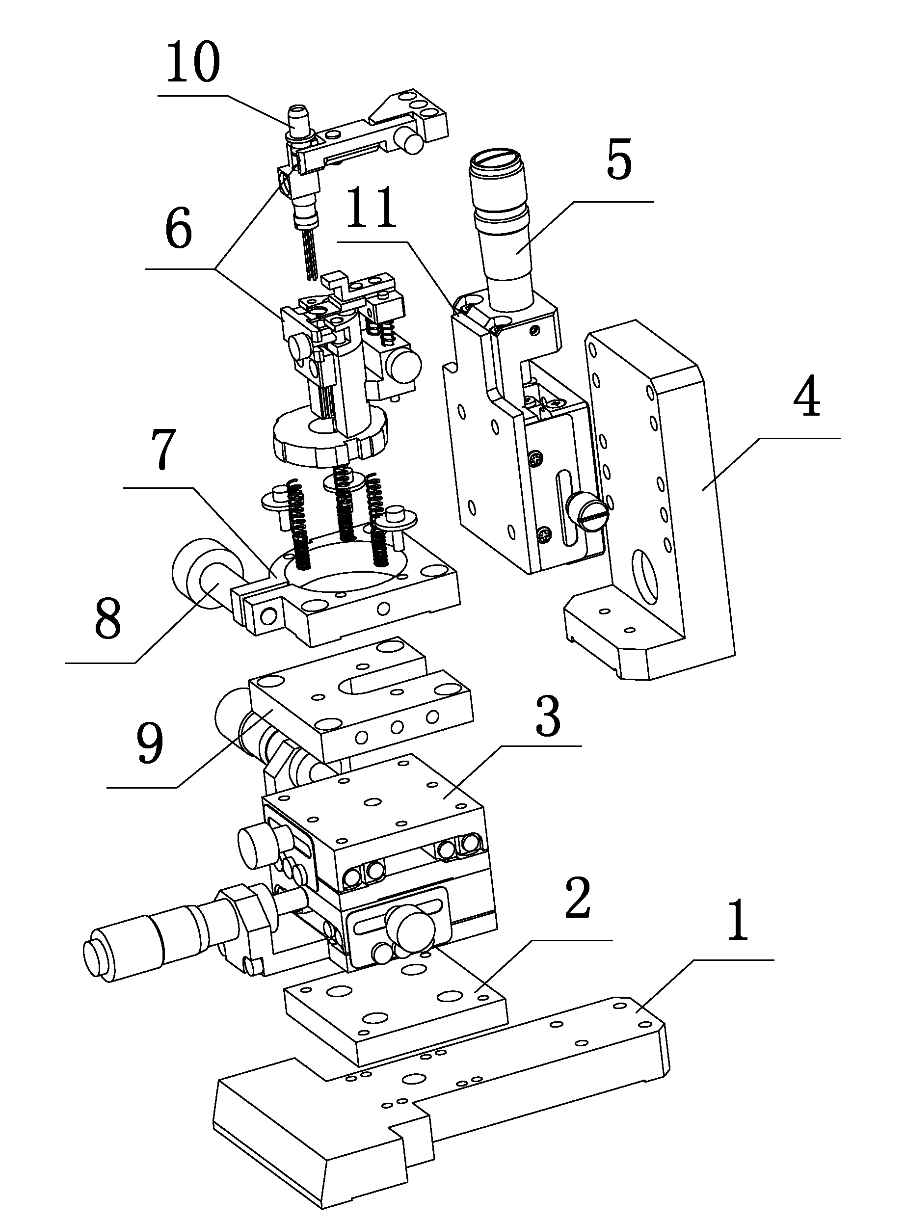
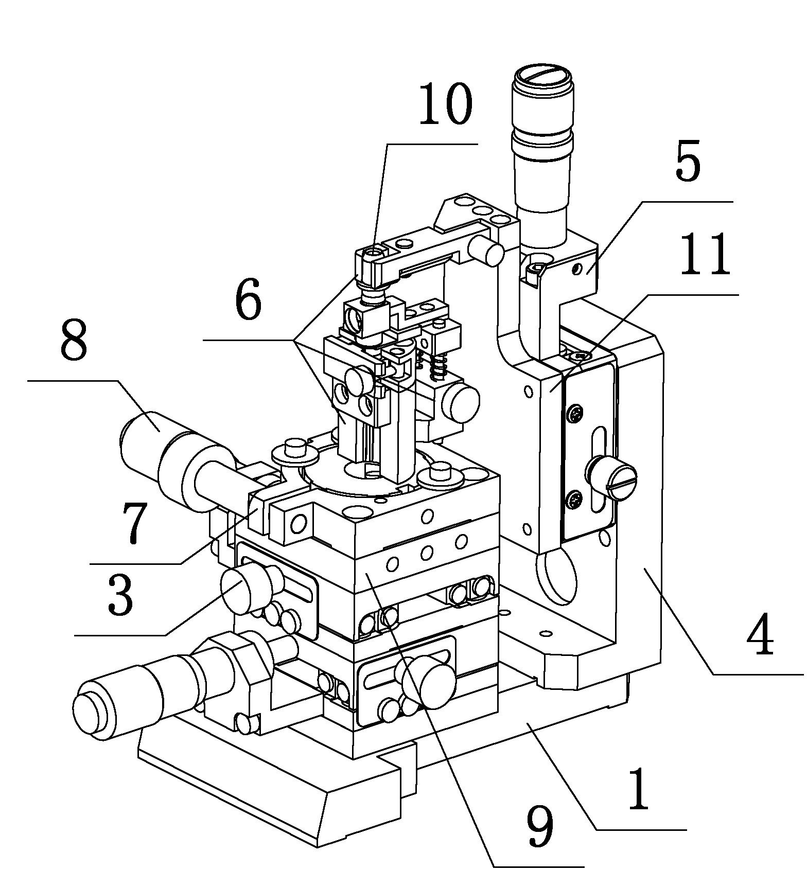
[0044] The present invention will be further described below in conjunction with accompanying drawing and specific implementation;

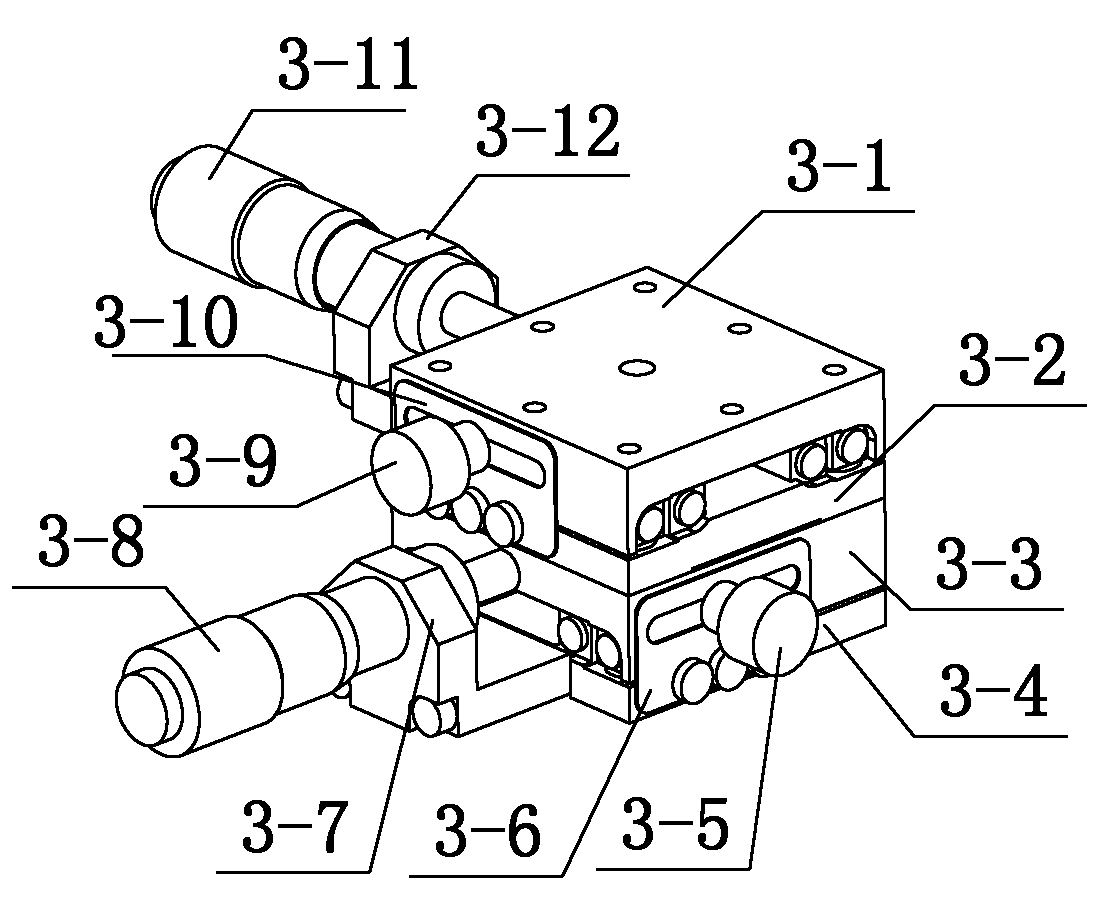
[0045] see Figure 1 to Figure 3 , a fixture for coupling welding of light-emitting devices, including a base plate 1, and also includes an XY horizontal moving platform 3, a Z sliding platform 5 and a clamping device 6, and the XY horizontal moving platform 3 is composed of an X horizontal moving platform, a Y horizontal The mobile platform consists of an X horizontal mobile platform and a Y horizontal mobile platform integrated; the XY horizontal mobile platform 3 is located above the bottom plate 1, and an adapter plate A2 is arranged between the XY horizontal mobile platform 3 and the bottom plate 1 . The X horizontal moving platform is provided with an X-direction fine-tuning screw A3-11 and a locking screw B3-5; the Y-direction moving platform is provided with a Y-direction fine-tuning screw B3-8 and a locking screw A3-9. The X horizontal ...


PUM


Abstract

The invention discloses a clamp for coupling a welding light-emitting device. The clamp comprises a bottom plate, an XY horizontal moving platform, a Z-axis sliding platform and a clamping device, wherein the clamping device is composed of an upper lifting component, a lower clamping component and an upper clamping component; the XY horizontal moving platform and the Z-axis sliding platform realize the fine adjustment of the welding component in the light-emitting device in longitudinal direction and transverse direction via fine adjustment screws. The clamp disclosed by the invention can realize the position adjustment of multi degree of freedom; the adaptability is strong and the flexibility is great; the alignments of ferrules, light component bases and laser diodes in X direction, Y direction and Z direction can be realized; the whole operation is convenient; the time for the coupling welding of the light-emitting device can be shortened, and the working efficiency is improved.

Description

technical field [0001] The invention relates to a fixture, which belongs to the field of coupling welding of light emitting devices. Background technique [0002] With the advent of the optical age, traditional cables are replaced by high-speed, basically lossless optical fibers in many applications. The optical transmitting and receiving devices are manufactured by encapsulating semiconductor or semiconductor optical receiver copper tubes with optical communication Standard structure product. Optical transmitting and receiving devices are mainly used in optical communication equipment. Optical transmitting devices are used to convert electrical signals into optical signals, and then connect to transmission media such as optical fibers through standard interfaces to complete the function of sending information. Optical receiving devices communicate with Optical fiber connection converts the signal transmitted in the optical fiber into an electrical signal to complete the fu...

Claims


Application Information

Patent Timeline
IPC IPC(8): B23K26/42B23K37/04B23K26/70
Inventor 黄昭彰吴兆丰
Owner SOURCE PHOTONICS CHENGDU
Features
  • Generate Ideas
  • Intellectual Property
  • Life Sciences
  • Materials
  • Tech Scout
  • Unparalleled Data Quality
  • Higher Quality Content
  • 60% Fewer Hallucinations
Learn More