Door type drilling machine

A drilling machine and drilling mechanism technology, applied in glass manufacturing equipment, glass cutting devices, glass production, etc., can solve the problems of moving to any position, unstable feeding, low efficiency, etc., to meet the needs of matching, The effect of improving work efficiency

Inactive Publication Date: 2011-10-12
武汉瑞林峰机器有限公司
View PDF4 Cites 10 Cited by
  • Summary
  • Abstract
  • Description
  • Claims
  • Application Information

AI Technical Summary

Problems solved by technology

[0002] Automotive glass drilling machines require complex control and positioning, while domestic horizontal glass drilling machines only have simple desktop single-head glass drilling machines, and there is no drilling positioning system, which requires manual marking and positioning, resulting in low efficiency. It cannot be used as a supporting equipment for a modern glass deep processing production line
In particular, there is no CNC drilling machine specifically for automotive glass processing in China. The drill bits of most glass drilling machines can only move on one line and cannot move to any position in one plane, especially the positioning of glass is mainly done manually. Lord, very inefficient
In addition, the rotary motor of the drill bit generally uses an ordinary motor, the speed is too low, the drilling effect cannot meet the requirements of the automobile glass, the feed of the drill bit is generally pneumatic, and the feed is not stable, which also affects the quality of the drilled hole, and the repair of the drill bit Grinding is manual and the efficiency is low
Moreover, the driving device of the existing drilling machine is arranged under the worktable, and the dripping of cooling water causes problems such as corrosion of the guide rail, which affects the service life of the equipment

Method used


Image

  • Door type drilling machine
  • Door type drilling machine
  • Door type drilling machine

Examples


Embodiment Construction

[0028] The technical solution of the present invention will be described in detail below in conjunction with the accompanying drawings and embodiments.

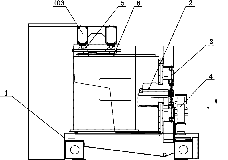
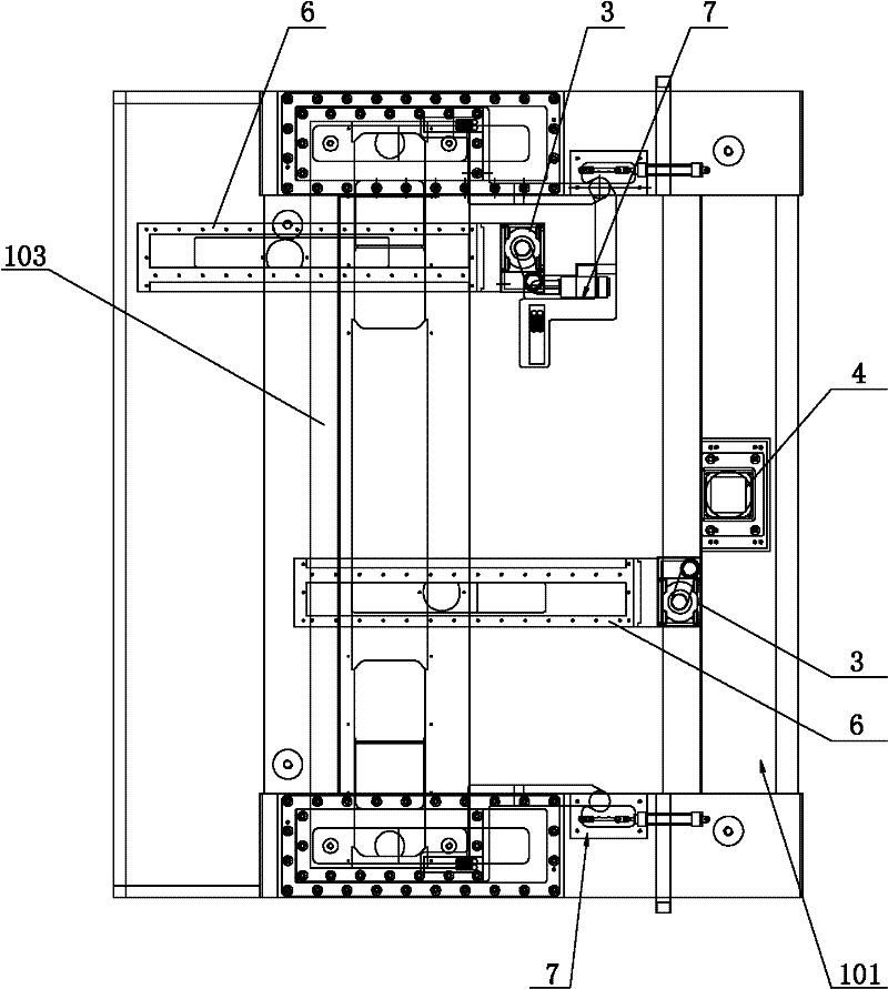
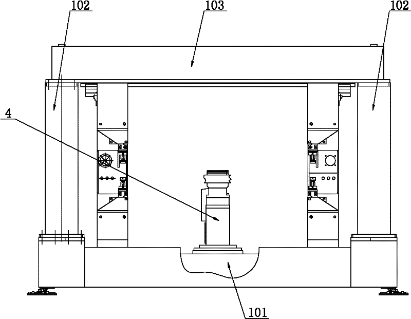
[0029] Such as figure 1 , figure 2 and image 3 As shown, the embodiment of the present invention provides a portal drilling machine, including a host and a control module, the host includes a frame 1, a positioning device, a clamping mechanism 2 and a drilling mechanism 3; the frame 1 includes a chassis 101 and is arranged on The uprights 102 on both sides on the chassis 101 and the beams 103 arranged on the uprights 102 on both sides; the positioning device includes a rotating mechanism 4, two sets of X-direction driving mechanisms 5 and two sets of Y-direction driving mechanisms 6; the rotating mechanism 4 is arranged at the front end of the host The lower part is fixed on the chassis 101 of the frame 1, the X-direction driving mechanism 5 is arranged on the beam 103, and the Y-direction driving mechanism 6 is arranged ...


PUM


Abstract

The invention relates to the technical field of drilling equipment, in particular to a door type drilling machine. The drilling machine comprises a host machine and a control module. The host machine comprises a machine frame, a locating device, a clamping mechanism and a drilling mechanism. The machine frame comprises a chassis, two lateral upright posts arranged on the chassis and transverse beams arranged on the two lateral upright posts. The locating device comprises a rotary mechanism, an X-directional driving mechanism and a Y-directional driving mechanism. The rotary mechanism is arranged at the lower part of the front end of the host machine and fixed on the chassis of the machine frame. The X-directional driving mechanism is arranged on the transverse beams. The Y-directional driving mechanism is arranged at the bottom of the X-directional driving mechanism. The clamping mechanism and the drilling mechanism are arranged on the Y-directional driving mechanism. The control module is connected with the rotary mechanism, the X-directional driving mechanism, the Y-directional driving mechanism, the clamping mechanism and the drilling mechanism. A drill in the door-type drilling machine disclosed by the invention is capable of freely moving in a glass plane. The fully automatic locating and drilling production is realized. The working efficiency is improved. Assorted requirements of production lines are satisfied.

Description

technical field [0001] The invention relates to the technical field of drilling equipment, in particular to a door type drilling machine for automobile glass. Background technique [0002] Automotive glass drilling machines require complex control and positioning, while domestic horizontal glass drilling machines only have simple desktop single-head glass drilling machines, and there is no drilling positioning system, which requires manual marking and positioning, resulting in low efficiency. It cannot be used as a supporting equipment for a modern glass deep processing production line. In particular, there is no CNC drilling machine specifically for automotive glass processing in China. The drill bits of most glass drilling machines can only move on one line and cannot move to any position in one plane, especially the positioning of glass is mainly done manually. Lord, very inefficient. In addition, the rotary motor of the drill bit generally uses an ordinary motor, the s...

Claims


Application Information

Patent Timeline
Patent Type & Authority Applications(China)
IPC IPC(8): C03B33/00
CPCY02P40/57
Inventor 郭锦文赵建文鲁兵才
Owner 武汉瑞林峰机器有限公司
Why Eureka
Try Eureka