Gasification cracking device based on electric induction heating and method for preparing sulfur gas

A technology of cracking device and gasification cracking furnace is applied in the fields of preparing high-temperature sulfur gas and gasification cracking device, which can solve the problems of external heating and the like, and achieve the effect of simple and perfect structure.

Active Publication Date: 2021-10-08
上海三夫工程技术有限公司
View PDF19 Cites 0 Cited by
  • Summary
  • Abstract
  • Description
  • Claims
  • Application Information

AI Technical Summary

Problems solved by technology

The invention adopts the induction heating method of the combination of inner and outer coils to solve the problem of equipment specification enlargement and large-scale engineering matching, and adopts the anti-magnetic structure to solve the problem of outward heating of the inner coil, and adopts magnetic materials with high temperature resistance, corrosion resistance and excellent magnetic properties. As an induction magnetic heating element, it solves the problems of high temperature resistance and corrosion resistance of the magnetic heating element, and selectively fills inert materials with high temperature resistance, corrosion resistance and high thermal conductivity as the heat transfer carrier to further solve the problem of heat transfer rate and efficiency.

Method used


Image

  • Gasification cracking device based on electric induction heating and method for preparing sulfur gas
  • Gasification cracking device based on electric induction heating and method for preparing sulfur gas
  • Gasification cracking device based on electric induction heating and method for preparing sulfur gas

Examples


Embodiment 1

[0082] Utilize the gasification and cracking device based on induction heating in the present invention to gasify and produce sulfur gas, the process is as follows:

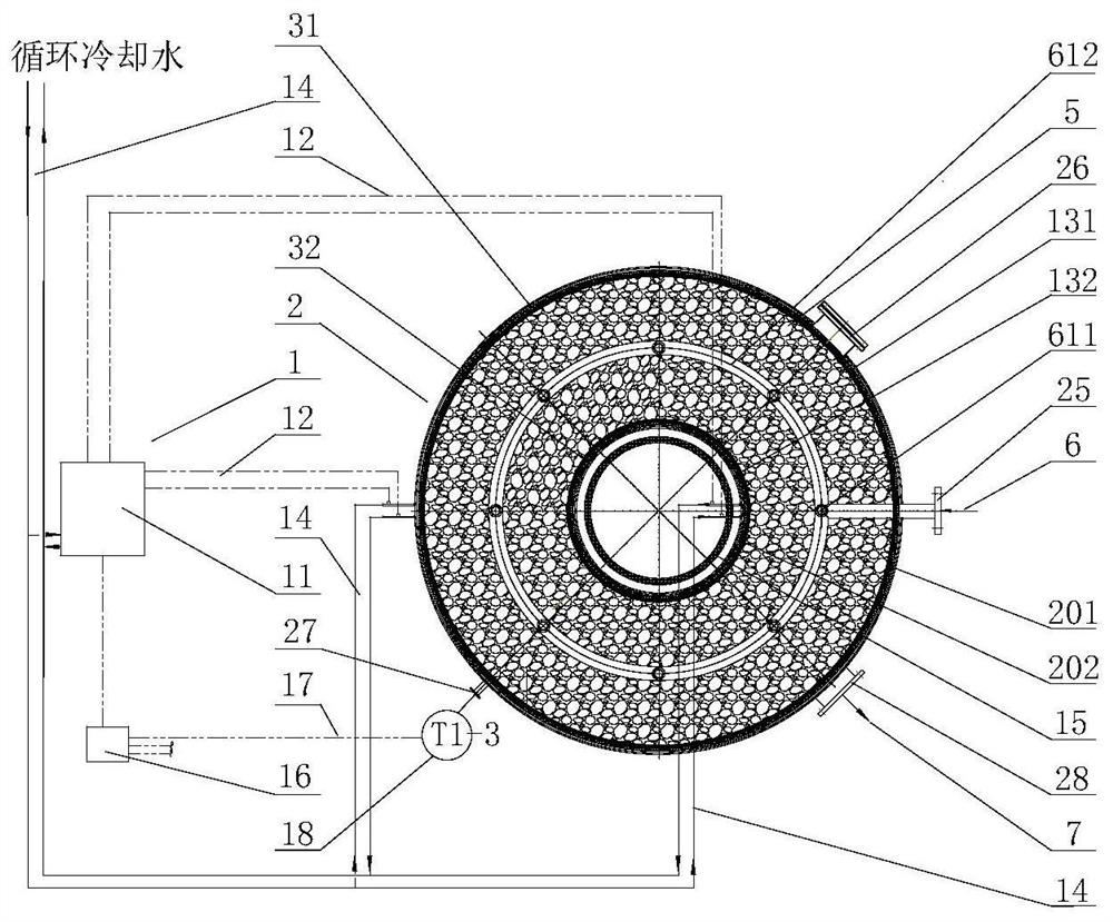
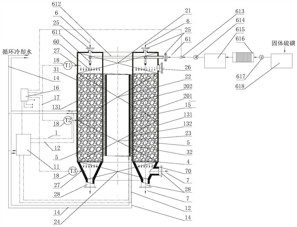
[0083] Such as image 3 , Figure 4 As shown, in this embodiment, solid sulfur is used as a raw material, which is indirectly heated and melted into liquid sulfur by a steam coil, and then sent to a sulfur filter 616 by a crude sulfur pump 617 to filter and remove solid and organic impurities. After filtering, the refined liquid sulfur is put into a refined sulfur storage Store in tank 615, then adjust and control the amount of sulfur through refined sulfur pump 614 and flow meter 613, and send the liquid material inlet 61 of gasification cracking furnace shell 2, directly atomized by atomizing nozzle 611, and pass through the external induction coil of gasification cracking furnace 131. Induction and heating of the inner induction coil 132 work together to gasify to obtain high-temperature sulfur gas.

[0084]...

Embodiment 2

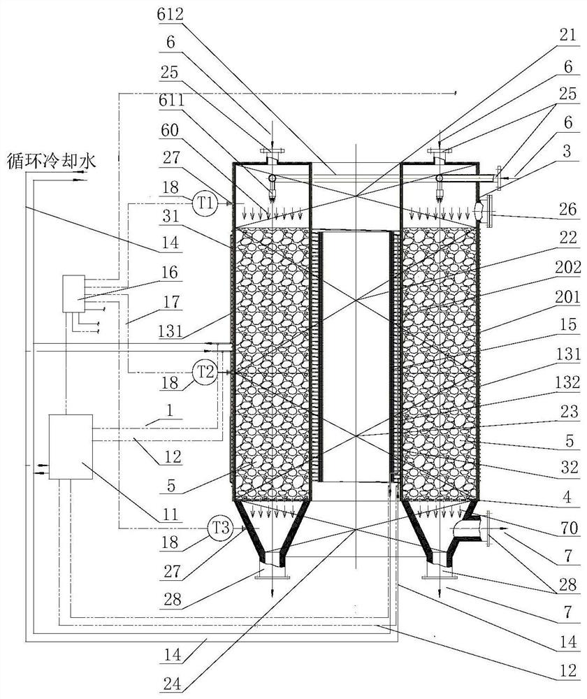
[0089] Such as Figure 5 , Figure 6 As shown, in this embodiment, the outer cylinder body 201 and the inner cylinder body 202 of the gasification cracking furnace are magnetically conductive heating elements, and their materials are chromium-molybdenum-nickel metal alloy, silicon carbide, graphite-silicon carbide composite material, silicon carbide-dicarbonate Molybdenum silicide composite material, silicon dioxide-molybdenum disilicide composite material, silicon carbide-zirconia composite material and other high temperature resistant magnetic materials, the heat transfer carrier 5 is made of honeycomb block molybdenum disilicide, vermiculite, One of silicon carbide, alumina ceramics and other high temperature resistant ceramics.

[0090] Using solid sulfur as the raw material, the solid sulfur particles enter the storage bin 626 for buffering, and after being stabilized by the feeder 625 and weighing equipment 624, they are sent to the screw extruder 623, and the solid sul...

Embodiment 3

[0096] Such as Figure 7 , Figure 8As shown, in this embodiment, liquid sulfur is used as a raw material, and the molten sulfur tank 618 uses heat conduction oil for indirect heating and heat preservation to maintain molten liquid sulfur, and the liquid sulfur is blown and atomized by pumping nitrogen; the outer cylinder 201 and the inner cylinder of the gasification cracking furnace 202 selects one of non-magnetic conductive ordinary ceramics, glass fiber reinforced plastics, and quartz glass. According to the needs of processing capacity and heating power, a plurality of small cylindrical magnetic heating elements 8 are arranged in the inner cavity. Silicon carbide, a combination of graphite and silicon carbide, silicon carbide-molybdenum disilicide composite material, silicon dioxide-molybdenum disilicide composite material, silicon carbide-zirconia composite material and other high temperature resistant magnetic materials, separator 4 Porous high-temperature resistant ce...


PUM

PropertyMeasurementUnit
melting pointaaaaaaaaaa
ignition pointaaaaaaaaaa
boiling pointaaaaaaaaaa

Abstract

The invention relates to a gasification cracking device based on electric induction heating and a method for preparing sulfur gas. The device comprises a gasification cracking furnace shell and an electric induction generation system, the gasification cracking furnace shell comprises an outer barrel and an inner barrel arranged in the outer barrel, the inner barrel and the outer barrel are both provided with magnetic conduction heating materials, a diamagnetic structure is arranged in the inner barrel, a feeding chamber, a vaporizing chamber, an overheating chamber and a discharging chamber are sequentially arranged between the inner barrel and the outer barrel from top to bottom, and the electric induction generating system comprises an induction coil. When sulfur gas is rapidly prepared, the vaporizing chamber and the overheating chamber are filled with heat transfer carriers, the induction coil is powered on, the magnetizer heats, heat is transferred to the heat transfer carriers to be heated, sulfur passes through the high-temperature magnetizer and the heat transfer carriers and absorbs heat of the high-temperature magnetizer and the heat transfer carriers, heating, vaporizing, cracking and overheating are completed, and a high-temperature sulfur gas product is prepared. Compared with the prior art, the device can meet the heating gasification requirements of various materials, especially materials needing ultrahigh-temperature gasification and cracking, and meets the matching requirements of large-scale industrial production.

Description

technical field [0001] The invention belongs to the technical field of gasification and cracking, and relates to a gasification and cracking device based on electric induction heating and a method for preparing high-temperature sulfur gas. Background technique [0002] The gasification and cracking furnace is a device used for gasification and cracking reaction of solid or liquid materials. For sulfur, waste sulfuric acid, organic matter, biomass, coal and other materials, the gasification and cracking process needs to be carried out in a high-temperature closed gasification and cracking furnace. [0003] Generally, the process requires the gasification and cracking furnace to quickly heat the reactants to a temperature of 300-1200 ° C or even higher to ensure short residence time of the medium, less side reactions in the process, high product yield, and stability and high efficiency. Heat supply and heat transfer, and economical and applicable high temperature and corrosio...

Claims


Application Information

Patent Timeline
Patent Type & Authority Applications(China)
IPC IPC(8): B01J19/00B01D1/00B01D1/16B01J19/02B01J19/14B01J19/24C01B17/02
CPCB01D1/0023B01D1/0082B01D1/16B01J19/24B01J19/0013B01J19/02B01J19/14C01B17/0226B01J2219/00139B01J2219/00058Y02P20/10
Inventor 张国兴庞仁杰储学群
Owner 上海三夫工程技术有限公司
Why Eureka
Try Eureka