
Shock-resistant ultrahigh-pressure pipe joint

A technology of high-pressure joints and pipe joints, applied in the direction of pipes/pipe joints/pipe fittings, sealing surface connections, mechanical equipment, etc., can solve the problems of poor seismic performance, hidden safety hazards, falling off, etc. simple effect

Pending Publication Date: 2021-12-17
DARDI INT CORP
View PDF0 Cites 0 Cited by
  • Summary
  • Abstract
  • Description
  • Claims
  • Application Information

AI Technical Summary

Problems solved by technology

[0004] The purpose of the present invention is to solve the problem that the existing ultra-high pressure water pipe joints have poor anti-seismic performance and are prone to safety hazards caused by circumferential vibration and falling off, and design a joint that can prevent axial loosening and falling off during the vibration process and prevent circumferential vibration from loosening. Detached anti-seismic ultra-high pressure pipe joints

Method used


Image

  • Shock-resistant ultrahigh-pressure pipe joint
  • Shock-resistant ultrahigh-pressure pipe joint
  • Shock-resistant ultrahigh-pressure pipe joint

Examples


Embodiment 1

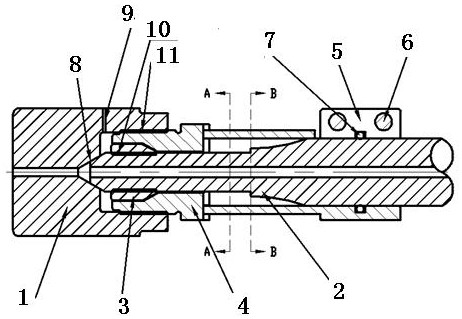
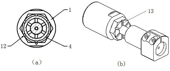
[0024] Such as Figure 2-4 shown.

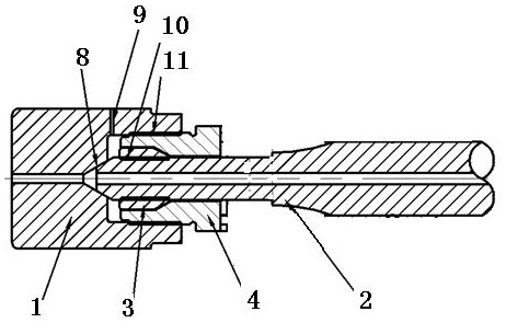
[0025] An anti-seismic ultra-high pressure pipe joint comprises a high pressure joint 1, a high pressure pipe 2, a screw washer 3 and a screw sleeve 4. The water inlet end of the water outlet hole of the high-pressure joint 1 has a frustum structure, and the water outlet end of the high-pressure pipe 2 has a frustum structure 8. Deliver high-pressure water to the high-pressure joint through a sealed channel; the high-pressure pipe 2 is covered with a screw washer 3, and the screw washer 3 is positioned in the inner cavity of the screw sleeve 4, and the screw sleeve 4 is fixed in the high-pressure joint 1 through threads, and the screw sleeve 4 is located The outer end of the high-pressure joint 1 has a hexagonal nut structure (such as image 3 ), to facilitate tightening, the thread direction of the screw washer 3 is opposite to the thread direction of the screw sleeve 4, and a safety pressure relief hole 9 is provided on the high-pressure...

Embodiment 2

[0028] The difference between this embodiment and Embodiment 1 is that the anti-rotation structure between the locking sleeve 5 and the high-pressure pipe 2 adopts a single key ( Figure 4 b), double bond ( Figure 4 c) or spline structure with ( Figure 4 d) instead of the rubber ring 7 ( Figure 4 a) structure, this key connection structure has stronger anti-rotation ability and better effect. In order to ensure the strength of the high-pressure pipe, it is best to thicken the pipe wall at the key connection position, and perform spot welding on the end surface.


PUM


Abstract

The invention discloses a shock-resistant ultrahigh-pressure pipe joint. The shock-resistant ultrahigh-pressure pipe joint comprises a high-pressure joint (1), a high-pressure pipe (2), a threaded gasket (3) and a threaded sleeve (4); the water inlet end of a water outlet hole of the high-pressure joint (1) is of a frustum hole structure, the water outlet end of the high-pressure pipe is of a frustum structure (8), the frustum structure (8) is matched with the frustum hole structure to achieve conical surface sealing, and high-pressure water in the high-pressure pipe is conveyed to the high-pressure joint through a sealing channel; and the high-pressure pipe (2) is sleeved with the threaded gasket (3), the threaded gasket (3) is positioned in an inner cavity of the threaded sleeve (4), the threaded sleeve (4) is fixed in the high-pressure joint (1) through threads, and the thread direction of the threaded gasket (3) is opposite to that of the threaded sleeve (4). The shock-resistant ultrahigh-pressure pipe joint is characterized in that a locking sleeve (5) is additionally arranged on the high-pressure pipe (2), a rubber ring (7) for increasing friction force is arranged between the locking sleeve (5) and the high-pressure pipe (2), and one end of the locking sleeve (5) is connected with the threaded sleeve (4). The shock-resistant ultrahigh-pressure pipe joint is simple in structure, convenient to manufacture, safe, reliable and long in service life.

Description

technical field [0001] The invention relates to an ultra-high pressure water jet technology, in particular to an ultra-high pressure water pipe connection technology for an ultra-high pressure water jet, in particular to an anti-seismic ultra-high pressure pipe joint. Background technique [0002] At present, combining ultra-high pressure water jet cutting technology with TBM shield machine technology, using the cutting function of supersonic water high-speed energy beam of ultra-high pressure water jet and the rolling crushing technology of shield machine can greatly improve the shield machine. The tunneling efficiency is the organic combination of these two technologies. However, the applicant found in the process of use that since this application not only requires ultra-high-pressure water jets, but usually uses a pressure of 100-600 MPa, and under such high pressures, the traditional connection method between the high-pressure pipe 2 and the high-pressure joint 1 cannot...

Claims


Application Information

Patent Timeline
Patent Type & Authority Applications(China)
IPC IPC(8): F16L19/02E21D9/06E21D9/10
CPCF16L19/0206F16L19/0218E21D9/0642E21D9/1066
Inventor 陈波朱家睿周彬
Owner DARDI INT CORP
Learn More