Mixed flow type water turbine with ultralow specific speed and high efficiency for cooling tower special belt water distributer

A technology with a water distributor and a cooling tower, which is applied in the direction of reaction engines, machines/engines, hydroelectric power generation, etc., can solve the problems of the shape, size and structure of the flow channel of the Francis turbine, and the complicated installation process, etc., to achieve compact structure, Stable operation and low noise effect

Inactive Publication Date: 2011-10-12
辽宁海思达科技发展有限公司
View PDF6 Cites 7 Cited by
  • Summary
  • Abstract
  • Description
  • Claims
  • Application Information

AI Technical Summary

Problems solved by technology

Moreover, due to the limited installation space, the flow channel shape, size and structure of Francis turbines for power generation need to be greatly changed

Method used


Image

  • Mixed flow type water turbine with ultralow specific speed and high efficiency for cooling tower special belt water distributer
  • Mixed flow type water turbine with ultralow specific speed and high efficiency for cooling tower special belt water distributer
  • Mixed flow type water turbine with ultralow specific speed and high efficiency for cooling tower special belt water distributer

Examples


Embodiment Construction

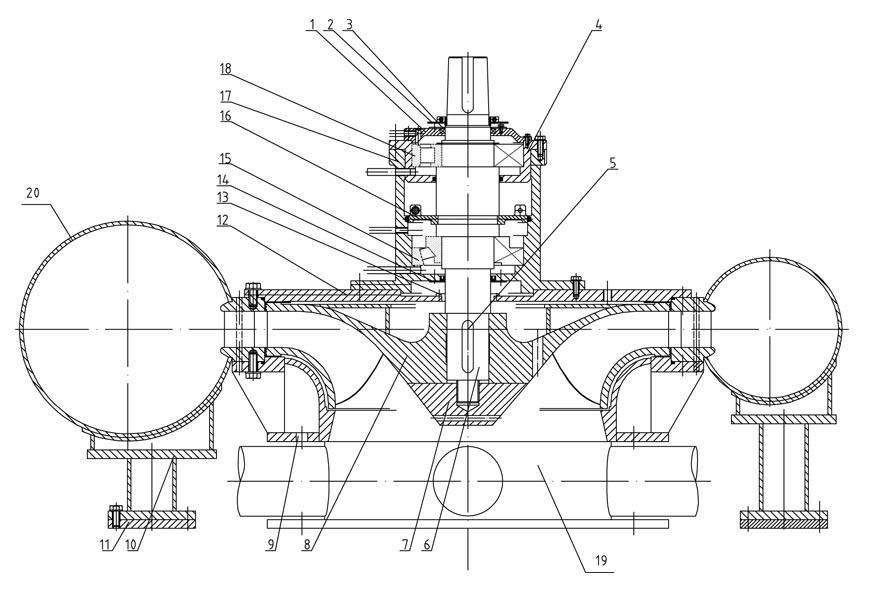
[0014] Ultra-low specific speed and high-efficiency Francis turbine with water distributor for cooling tower, which includes runner 8, main shaft 6, bearing device, seat ring 10, bottom ring 9, cover plate 12, bearing device includes first gland 3, bearing Cover 1, bearing cup 4, radial bearing 18, snap ring 16, thrust bearing 15, second gland 14, wherein the first gland 3, bearing cap 1, bearing cup 4, radial bearing 18, snap ring 16, The thrust bearing 15 and the second gland 14 are installed on the main shaft 6 from top to bottom in turn, and the radial bearing 18 is in the bearing cup 4, the thrust bearing 15 is directly installed in the sleeve 17, and the bearing cup 4 is fastened by bolts. On the sleeve 17, the bearing cover 1 is equipped with a skeleton seal, which is sealed with the first gland 3, and the water throwing ring 2 is installed above the first gland 3, and fixed on the main shaft 6 through a half-flange. The bearing device is placed in the sleeve 17, the sl...


PUM


Abstract

The invention relates to a mixed flow type water turbine with ultralow specific speed and high efficiency for a cooling tower special belt water distributer and relates to a novel energy-saving hydrodynamic device used for a cooling tower. The novel energy-saving hydrodynamic device comprises a rotating wheel, a main shaft, a bearing device, a stand ring, a base ring and cover plates, wherein the lower part of the base ring is connected with a water distributor, and the stand ring is formed by welding an volute, a guide vane, the upper cover plate and the lower cover plate into a whole. The mixed flow type water turbine provided by the invention has the characteristics of novel structure, stable operation, small noise, large flow capacity, high efficiency, energy conservation and environmental friendliness; the rotating wheel and each overflowing part of the water turbine are subjected to optimum design by adopting a CFD (computational fluid dynamic) three-dimensional flow turbulence unsteady constant analogue method, the geometric parameter of the rotating wheel and guide vane of the water turbine is set as follows: the ratio of the rotating wheel inlet diameter D1 to the rotating wheel outlet diameter D2 is equal to 1.508, the ratio of the rotating wheel height B0 to the rotating wheel inlet diameter D1 is equal to 0.20, the relative height of the guide vane O is equal to 0.09D1, the rotating wheel performance indexes meet the conditions that the specific speed ns=(50-70) m.kW, the unit speed n11=(45-55) r/min, the efficiency eta m=(88.5%-90.5%); and the key problem that the rotating wheel specific speed of the existing water turbine is overhigh and can not be matched with the cooling tower fan parameters if not being regulated by the planetary reducer is solved.

Description

technical field [0001] The invention belongs to the field of new energy-saving hydrodynamic equipment for cooling towers. Specifically, it is an ultra-low specific speed, low unit speed, and high-efficiency Francis water turbine with a water distributor dedicated to cooling towers. It uses the residual energy of circulating water without using The planetary gear reducer can directly drive the fan, thus replacing the motor as the power of the fan. Background technique [0002] The fan cooling system of the traditional cooling tower is composed of motor, drive shaft, bevel gear reversing device, planetary gear reducer, fan and other components. It has complex structure, poor reliability, high power consumption and high operating noise; The maintenance cost of the device is high. Therefore, the traditional cooling method of using a motor to drive a fan is neither environmentally friendly nor energy-saving. [0003] In view of the fact that the performance and efficiency of th...

Claims


Application Information

Patent Timeline
IPC IPC(8): F03B13/00F03B3/18F03B11/06
CPCY02E10/20
Inventor 何国仁陈远征
Owner 辽宁海思达科技发展有限公司
Why Eureka
Try Eureka