Novel multi-layer structure of rotor core

A rotor core and multi-layer structure technology, applied in the direction of magnetic circuit shape/style/structure, magnetic circuit rotating parts, etc., can solve the problems of motor stop rotating, broken contact parts, small local gaps, etc.

Inactive Publication Date: 2011-10-12
TIANJIN SANTROLL ELECTRIC SCI & TECH
View PDF6 Cites 11 Cited by
  • Summary
  • Abstract
  • Description
  • Claims
  • Application Information

AI Technical Summary

Problems solved by technology

[0003] The main disadvantage of the surface-protruding rotor is that the structural adhesive layer is applied between the magnet steel and the upper surface of the rotor core. Since the design of the magnet steel and the rotor core surface generally only leaves a gap of about 0.05, but because the best domestic magnet steel The manufacturer's processing accuracy can only be guaranteed at ±0.04mm, and the tolerance of the outer diameter of the rotor after lamination is also +0.02-+0.05mm, so there must be a local gap that is too small after pasting, resulting in some structural glue rare or missing
[0004] After research, the reason for the phenomenon that the magnetic steel is usually thrown out and broken is that when the high-speed operation is performed, the local magnetic steel is not firmly attached to the surface of the rotor core, and is thrown out by centrifugal force a little, hitting the stator core, causing the contact part to be broken. Splashed magnets block the air gap and stop the motor

Method used


Image

  • Novel multi-layer structure of rotor core
  • Novel multi-layer structure of rotor core
  • Novel multi-layer structure of rotor core

Examples


Embodiment Construction

[0011] The present invention will be further described below in conjunction with accompanying drawing and specific embodiment:

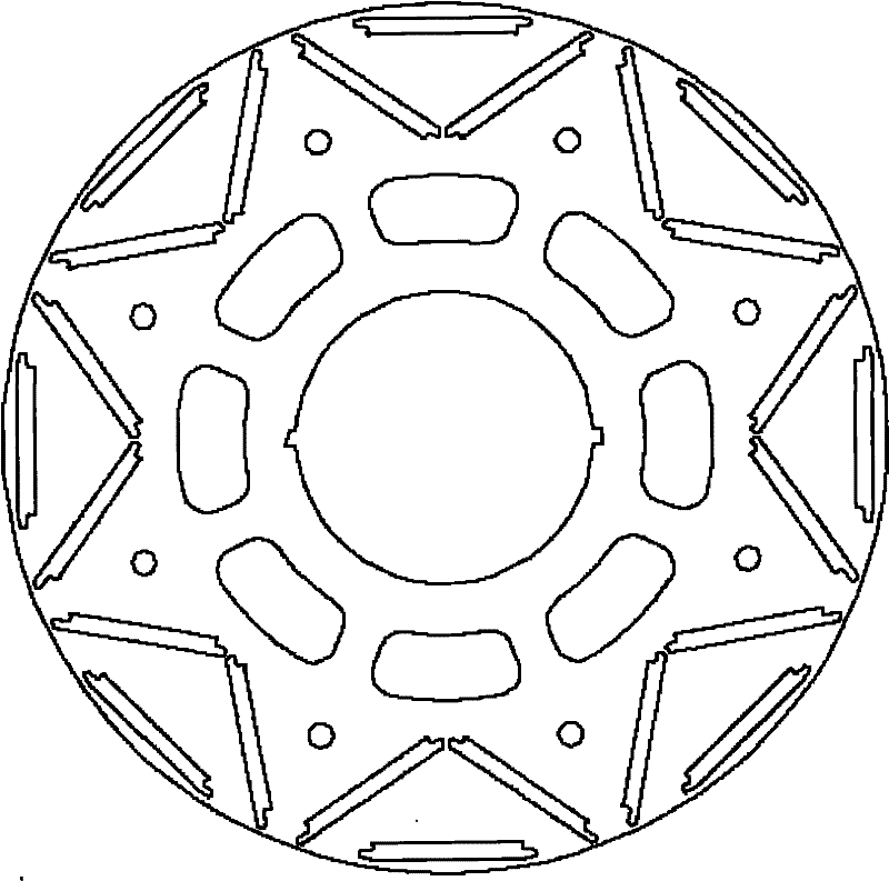
[0012] Such as figure 1 , When designing the rotor, a double-layer structure is adopted. The first layer is composed of a straight-shaped magnetic steel, and the second layer of magnetic steel adopts a V-shaped structure. By rationally designing the length of the magnets and the distance between the magnets, the magnetic flux can be output to the greatest extent, and the similarity between the back EMF waveform and the sine wave can reach 1.02-1.04.

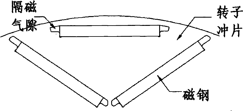
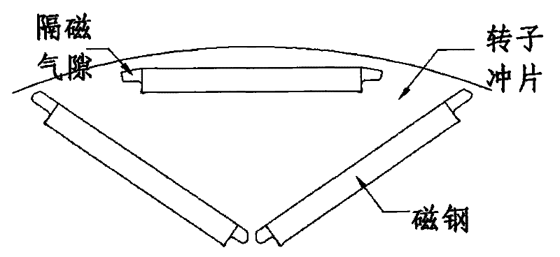
[0013] Such as figure 2 , The magnetic isolation air gap is reasonably designed, and the magnetic isolation air gap consists of a curve or a straight line to form a closed figure to ensure that the magnetic flux leakage is minimized.

[0014] Utilize the technical solution described in the present invention, or those skilled in the art design a similar technical solution under the inspiration of the ...


PUM


Abstract

The invention relates to a novel multi-layer structure of a rotor core. The novel multi-layer structure of the rotor core is formed by laminating punched silicon-steel sheets and embedding magnetic steel. During the design of a rotor, a double-layer structure is adopted, wherein the first layer comprises a piece of linear magnetic steel; and the second layer of magnetic steel has a V-shaped structure. Magnetic flux can be output to a largest extent by reasonably designing the length of the magnetic steel and distances between the respective magnetic steel, and the similarity of a counter potential wave form and a sine wave reaches 1.02 to 1.04. In a novel multi-layer embedded rotor sheet, on the basis of reserving the conventional advantages that a motor smoothly operates at a speed of 8,000 rpm, by the unique multi-layer structure of the rotor, the output of the magnetic flux of each electrode can be guaranteed to a largest extent, and the volume of the magnetic steel cannot be greatly increased.

Description

technical field [0001] The invention belongs to the field of permanent magnet synchronous motors and relates to a multi-layer structure of a novel rotor core. Background technique [0002] Now commonly used permanent magnet synchronous motor rotor core sub-surface type and embedded type. Existing surface rotor structures are divided into protruding and embedded, and permanent magnets provide the direction of magnetic flux. The surface of the protruding rotor core is pasted with tile-shaped magnetic steel, and the outer surface of the permanent magnet and the inner circle of the stator core are generally only covered with a non-magnetic cylinder for protection, or the surface of the permanent magnet poles is covered with a non-woven glass ribbon for protection. This is to prevent the rotor magnetic steel from detaching from the rotor core under the joint action of centrifugal force and electromagnetic torque when the rotating speed exceeds 5000rpm. There is a ferromagnetic ...

Claims


Application Information

Patent Timeline
Patent Type & Authority Applications(China)
IPC IPC(8): H02K1/27
Inventor 王晔辉陈鹏
Owner TIANJIN SANTROLL ELECTRIC SCI & TECH
Why Eureka
Try Eureka