
Wireless optical communication pulse position modulation detection and demodulation method based on least posterior error probability

A technology of pulse position modulation and error probability, which is applied in the direction of error prevention, electromagnetic wave transmission system, digital transmission system, etc., and can solve the problems that the performance advantages of soft iterative decoding cannot be brought into play

Active Publication Date: 2011-10-12
中国人民解放军海军航空大学航空作战勤务学院
View PDF6 Cites 11 Cited by
  • Summary
  • Abstract
  • Description
  • Claims
  • Application Information

AI Technical Summary

Problems solved by technology

However, when the system introduces error correction coding and adopts soft iterative decoding, what is required to be sent to the decoder is the likelihood information of the detected and demodulated bits, which cannot be provided by the current PPM detection and demodulation methods
Therefore, the existing PPM detection and demodulation methods combined with error correction coding will not be able to take advantage of the performance advantages of soft iterative decoding

Method used


Image

  • Wireless optical communication pulse position modulation detection and demodulation method based on least posterior error probability
  • Wireless optical communication pulse position modulation detection and demodulation method based on least posterior error probability
  • Wireless optical communication pulse position modulation detection and demodulation method based on least posterior error probability

Examples


Embodiment 1

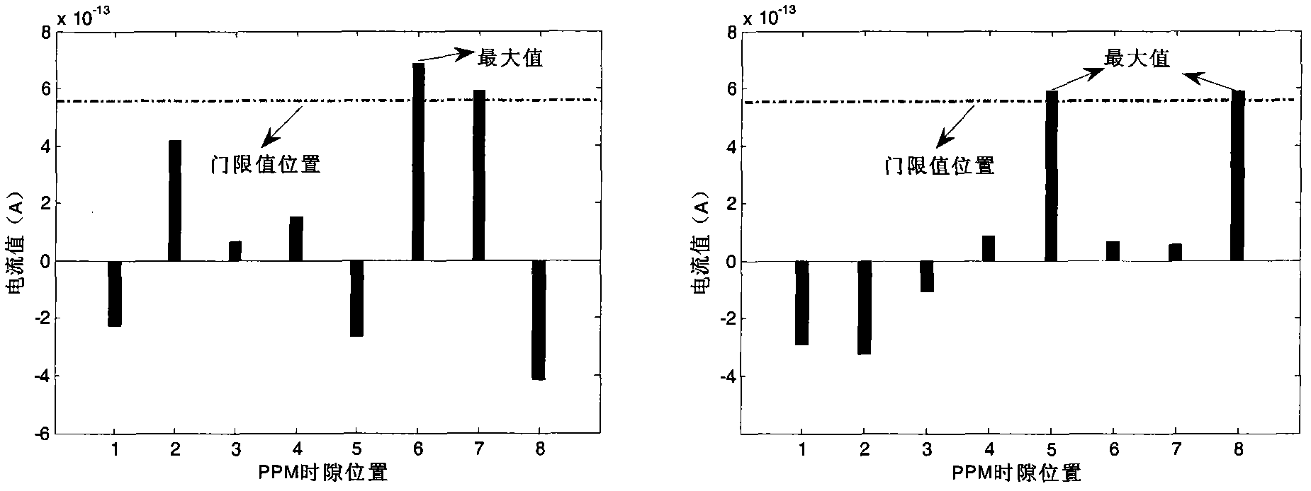
[0030]The wireless optical communication system adopts the PPM modulation mode, and the modulation order M=3. The position of the optical pulse in the symbol after the information bit group is modulated by PPM is shown in Table 1. The modulated signal is transmitted in turbulence and is affected by the noise of the receiving circuit at the receiving end. Therefore, the wireless optical communication channel is a cascade of turbulent atmospheric channel and Gaussian channel. Strong flicker follows a lognormal distribution:

[0031] f ( S ) = 1 2 2 π σ χ S exp { - ( ln S S 0 ...

Embodiment 2

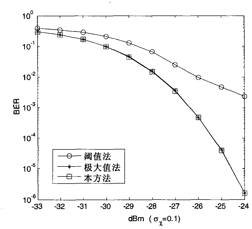
[0050] Under the communication conditions of the first embodiment, channel error correction coding and coding are added to the system to improve system error performance. Among them, add a (63, 51) before PPM modulation at the sending end 2 After PPM detection and demodulation at the receiving end, a soft iterative block decoder is added for decoding, and the decoding iteration takes 3 times. This kind of product code using soft iterative decoding method is also called TPC code, PPM The detection and demodulation methods adopt the present invention, the threshold value detection and demodulation method and the maximum value detection and demodulation method respectively.

[0051] According to the steps in the first embodiment, the received PPM symbols are detected and demodulated, and the obtained likelihood metric values ​​are sent to the TPC code decoder for iterative decoding without being judged. This method combines the error performance curve of the TPC code with the ma...


PUM


Abstract

The invention discloses a wireless optical communication pulse position modulation (PPM) detection and demodulation method based on least posterior error probability. The detection and the demodulation of the PPM are realized through the steps of dividing modulation position sets, calculating receiving bit posterior probability, calculating likelihood measure and performing binary judgment estimation. In a wireless optical communication system not using error correction encoding, the method is more effective than a threshold detection and demodulation method and has the performance equivalentto that of a maximum detection and demodulation method; in a system using soft iterative error correction encoding, the bit likelihood measure acquired by the method is used for iterative encoding, so that the method is superior to the situation of combination of the maximum detection and demodulation method as well as the threshold detection and demodulation method and the soft iterative error correction encoding; and therefore, the error performance of the atmospheric wireless optical communication system is effectively improved.

Description

technical field [0001] The invention relates to a pulse position modulation detection and demodulation method in a wireless optical communication digital pulse modulation system, in particular to a calculation method for the likelihood measure of received bits under pulse position modulation. Background technique [0002] At present, the wireless optical communication generally adopts the intensity modulation / direct detection system, and its modulation methods mainly include analog modulation and digital pulse modulation. Detect resume send sequence. Pulse position modulation (PPM) is a modulation method that uses the relative position of the light pulse to transmit information. Specifically, it modulates the binary information bits in groups, and each group has M the same number of bits. Each group Binary information bits correspond to 2 M time slots, the 2 M Only one of the time slots sends optical pulses, and the rest of the time slots do not send optical pulses. Using...

Claims


Application Information

Patent Timeline
IPC IPC(8): H04L1/00H04B10/12H04B10/524
Inventor 王红星胡昊徐建武孙晓明刘敏
Owner 中国人民解放军海军航空大学航空作战勤务学院
Learn More