High-magnetic-field-intensity pipeline deironing device capable of cleaning automatically

A magnetic field strength, automatic cleaning technology, applied in the direction of magnetic separation, chemical instruments and methods, solid separation, etc., can solve the problems of weakened iron removal effect, reduced iron removal efficiency, low magnetic field strength, etc., to achieve good iron removal effect and use The effect of long life and high magnetic field strength

Inactive Publication Date: 2011-10-19
马鞍山起劲磁塑科技有限公司
View PDF4 Cites 10 Cited by
  • Summary
  • Abstract
  • Description
  • Claims
  • Application Information

AI Technical Summary

Problems solved by technology

[0002] The existing pipeline iron remover used in the production of chemical industry, glass, ceramics, refractory materials, food and other industries usually uses pipeline manual iron remover, and its working principle is: separate the inlet and outlet of the pipeline iron remover It is installed on the pipeline for conveying materials with a flange. The material in the pipeline enters from the feed port of the iron remover, and the ferromagnetic impurities mixed in the material are absorbed by the magnetic field generated by the permanent magnet assembly installed on the side or in the middle of the iron remover. On the surface of the magnet, although the iron removal effect of this pipeline iron remover is good, it must be shut down after a period of use, and the ferromagnetic impurities adsorbed on the magnetic plate must be manually removed. If it is not removed in time, it will easily form a blockage and seriously weaken t

Method used


Image

  • High-magnetic-field-intensity pipeline deironing device capable of cleaning automatically
  • High-magnetic-field-intensity pipeline deironing device capable of cleaning automatically
  • High-magnetic-field-intensity pipeline deironing device capable of cleaning automatically

Examples


Embodiment Construction

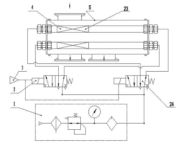
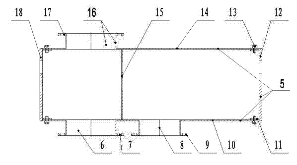
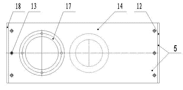
[0016] From Figure 1-Figure 6It can be seen from the figure that: a high magnetic field strength self-cleaning pipeline iron remover is characterized in that: the high magnetic field strength self-cleaning pipeline iron remover is mainly composed of a box body 5, a magnet device, a pneumatic device and an electric control device 3, the The box body 5 is rectangular and is made of stainless steel plate. Its upper side panel 14, lower side panel 10 and front and rear side panels are welded into one after bending stainless steel sheets, and the upper side panel 14 and the lower side panel The left and right ends of 10 are evenly distributed to offer bolt through holes respectively, and the upper and lower ends of the left and right end panels 18,12 inner surfaces are respectively welded elongated mounting plates 11, and on each mounting plate 11 corresponding to the upper and lower The positions of the bolt through holes on the side panels 14, 10 are respectively provided with m...


PUM


Abstract

The invention discloses a high-magnetic-field-intensity pipeline deironing device capable of cleaning automatically, belonging to deironing devices. The deironing device is characterized by mainly consisting of a box body, a magnetic body device, a pneumatic device and an electrically control device; the box body is of a rectangle; a feed inlet pipe arranged above, a discharge pipe arranged below and a deironing pipe are welded on an upper side panel and a lower side panel of the box body; an inner baffle plate is welded at the right side of the feed pipe and the discharge pipe in the inner cavity of the box body; axial mounting holes are arranged in rows symmetrically on a left end panel, a right end panel and the inner baffle plate of the box body; magnet devices composed of sleeve pipes and magnetic bars penetrate in each axial mounting hole on a coaxial central line; a feed blocking ring is welded on a middle section of each sleeve pipe; the left end and the right end of each sleeve pipe are connected with a pneumatic device which is composed of an air compressor, a left two-position five-way pneumatic electromagnetic valve and a right two-position five-way pneumatic electromagnetic valve; and compressed air is induced in each sleeve pipe to drive the magnetic bar to move left to right to absorb iron and perform deironing. The pipeline deironing device has high magnetic field strength, good deironing effect and long service life.

Description

technical field [0001] The invention belongs to a pipeline iron remover, in particular to a pipeline iron remover with high magnetic field strength. Background technique [0002] The existing pipeline iron remover used in the production of chemical industry, glass, ceramics, refractory materials, food and other industries usually uses pipeline manual iron remover, and its working principle is: separate the inlet and outlet of the pipeline iron remover It is installed on the pipeline for conveying materials with a flange. The material in the pipeline enters from the feed port of the iron remover, and the ferromagnetic impurities mixed in the material are absorbed by the magnetic field generated by the permanent magnet assembly installed on the side or in the middle of the iron remover. On the surface of the magnet, although the iron removal effect of this pipeline iron remover is good, it must be shut down after a period of use, and the ferromagnetic impurities adsorbed on th...

Claims


Application Information

Patent Timeline
IPC IPC(8): B03C1/02
Inventor 周国胜严启许爱瑾
Owner 马鞍山起劲磁塑科技有限公司
Why Eureka
Try Eureka