
Physical sewage treatment system used for sewage treatment from source

A sewage treatment system and physical technology, applied in the field of sewage and sewage treatment system, can solve the problems of long sewage interception pipeline, difficult land acquisition and demolition, uneven distribution of fresh water resources, etc., and achieve the effect of easy treatment.

Inactive Publication Date: 2011-10-19
ZHONGSHAN JUYA BATHROOM CO LTD
View PDF6 Cites 13 Cited by
  • Summary
  • Abstract
  • Description
  • Claims
  • Application Information

AI Technical Summary

Problems solved by technology

The problems of such a treatment process are: the equipment used occupies a large area, the sewage interception pipeline is long, the construction cost is high, the equipment investment is huge, the operating cost is high, and the land acquisition and demolition are difficult. It is difficult to adopt for a small and medium-sized enterprise and a residential area This method is used for sewage treatment, and the popularization and application of this high-input, high-operating-cost treatment process has certain limitations.
[0005] In addition, due to the fact that the available fresh water on the earth is relatively small compared to the increasing water demand of our human beings, coupled with the uneven distribution of fresh water resources and increasingly serious water pollution, the available fresh water is further reduced , resulting in a severe shortage of water resources available globally

Method used


Image

  • Physical sewage treatment system used for sewage treatment from source
  • Physical sewage treatment system used for sewage treatment from source
  • Physical sewage treatment system used for sewage treatment from source

Examples


Embodiment 1

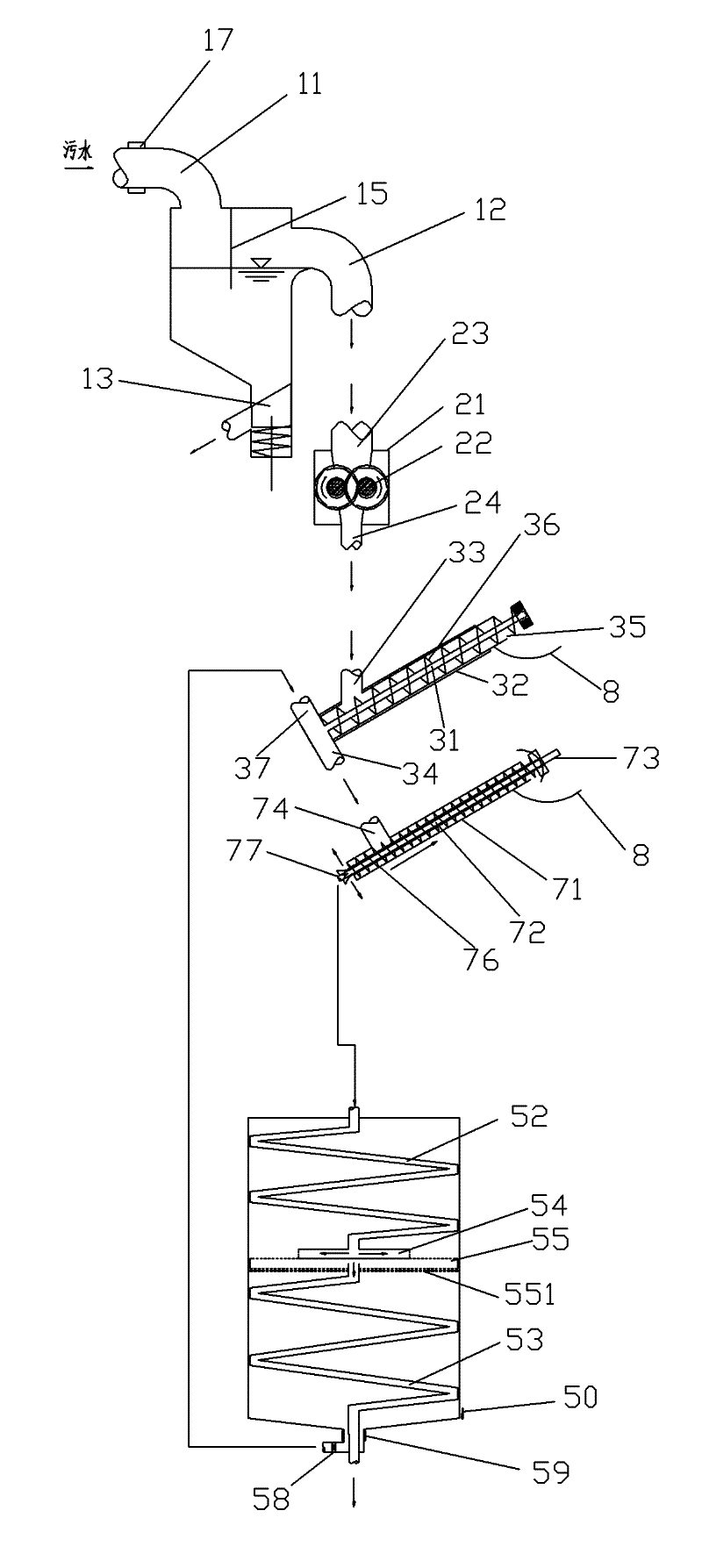
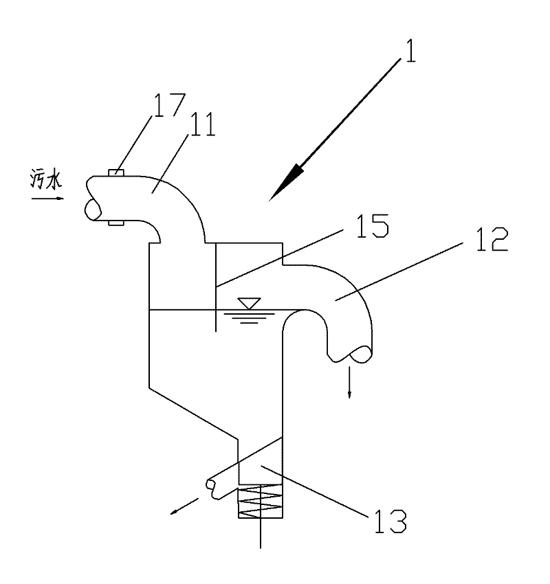
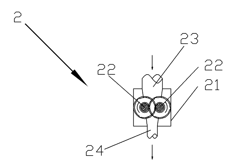
[0069] Figure 1-11 The shown physical sewage and sewage treatment system that can be used for source pollution control is an embodiment of the present invention, which is composed of a solid-liquid separation device and a sedimentation device 5 connected. The solid-liquid separation device has a solid-liquid separator and its separated water inlet, separated water outlet and separated sewage outlet.

[0070] The solid-liquid separation device is composed of a settling device 1, a crushing device 2 and a spiral solid-liquid separator connected in sequence. Wherein the settling device 1 is a container with a settling water inlet 11, a settling overflow 12 and a settling sewage valve 13, wherein the settling overflow 12 is located at the top of the settling device 1, and serves as a separation outlet of the solid-liquid separation device. The settlement water inlet 11 is located on the top of the settlement device 1 and is used for connecting the sewage outlet of the outside wo...

Embodiment 2

[0078] like Figures 12 to 14 The shown physical sewage and sewage treatment system that can be used for source pollution control is different from the second embodiment in that the secondary spiral water outlet 77 of the secondary spiral solid-liquid separator 7 and the water inlet hose 52 of the sedimentation device 5 A circulating water tank 4 is arranged between the water inlets of the water inlet, so that the sewage from the solid-liquid separation device can be preliminarily settled in the circulating water tank 4 before entering the sedimentation device 5, and the water flow rate entering the sedimentation device 5 can also be slowed down. like Figure 14 As shown, the circulating water tank 4 has a water tank water inlet 41 , a first water tank outlet pipe 42 and a second water tank outlet pipe 43 . Wherein, the water tank water inlet 41 is located at the top of the circulating water tank 4 and is connected to the water outlet 72 of the secondary spiral solid-liquid s...

Embodiment 3

[0080] Different from Example 1, Figures 15-17 The shown physical sewage and sewage treatment system that can be used for source pollution control has added a bionic intestinal filter device 6 .

[0081] like Figure 16 and 17 As shown, the bionic intestinal filter device 6 is composed of a filter housing 61, an intestinal tubular filter mechanism, a filter sewage outlet, a filter water inlet, a filter water outlet 63, a high-pressure pump 66, a mud pump 65 and a sludge hydrometer 67. . The filtered water outlet 63 is located at the bottom of the filter housing 61 , and a water outlet valve is arranged at the filtered water outlet 63 . The intestinal tubular filter membrane mechanism is composed of 6 layers of tubular filter membrane units communicated by the connecting piece 60, and each layer of tubular filter membrane unit is connected by the connecting piece 60 and arranged side by side. The brush mechanism is composed. The water inlet end of the first layer of tubul...


PUM


Abstract

The invention discloses a physical sewage treatment system used for sewage treatment from the source, comprising a solid-liquid separation device and a settling device. The solid-liquid separation device is provided with a solid-liquid separator, and a separation water inlet, a separation water outlet and a separation sewage discharging port of the solid-liquid separator; the settling device comprises a settling shell the bottom of which is provided with a settling sewage discharging port, a water inlet hose and a water outlet hose are arranged in the settling shell, the water inlet end of the water inlet hose is connected with the separation water outlet of the solid-liquid separation device, the water outlet end of the water inlet hose is connected with a hollow floating disk, the outline of the floating disk adapts to that of the cross section of the settling shell, and a plurality of through holes are uniformly distributed in the annular area of the bottom surface, close to the edge; a floating disk water outlet is arranged on the bottom of the floating disk and is connected with the water inlet end of the water outlet hose, and the water outlet end of the water outlet hose extends out of the settling shell. The sewage treatment system can be used for treating sewage timely from the pollution sources, thus reducing or avoiding the phenomenon that sewage enters public water body.

Description

technical field [0001] The invention relates to a sewage and sewage treatment system, in particular to a physical sewage and sewage treatment system which can be used for source pollution control. Background technique [0002] At present, some production and domestic sewage are directly discharged, which not only wastes water resources, but also affects the natural environment; some are discharged after being treated by setting up sewage treatment plants. As for the treatment of industrial and civil sewage, a traditional physical treatment method is to complete the whole process of sewage treatment by passing the discharged sewage through sedimentation tanks, advection tanks, filtration devices, concentration tanks, and mud-water separation devices. The problems of such a treatment process are: the equipment used occupies a large area, the sewage interception pipeline is long, the construction cost is high, the equipment investment is huge, the operating cost is high, and th...

Claims


Application Information

Patent Timeline
IPC IPC(8): C02F9/02
Inventor 谢水清
Owner ZHONGSHAN JUYA BATHROOM CO LTD
Learn More