Machine housing of a hydraulic machine

A technology of fluid machinery and casing, which is applied in the field of casing of fluid machinery, and can solve problems such as wrong assembly and damage of the casing cover, and achieve the effects of low measurement cost, simple manufacturing, and low manufacturing cost

Active Publication Date: 2011-10-19
ROBERT BOSCH GMBH
View PDF10 Cites 0 Cited by
  • Summary
  • Abstract
  • Description
  • Claims
  • Application Information

AI Technical Summary

Problems solved by technology

By fitting the housing cover onto the housing segment 180 degrees offset from said axis, incorrect assembly of the housing cover may result
This incorrect assembly can cause damage when using fluid machines, or require additional assembly costs to correctly set the housing cover

Method used


Image

  • Machine housing of a hydraulic machine
  • Machine housing of a hydraulic machine
  • Machine housing of a hydraulic machine

Examples


Embodiment Construction

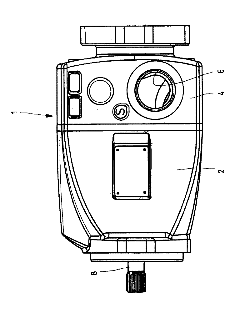
[0018] figure 1 An exemplary embodiment of the housing 1 of the fluid machine according to the invention is shown in side view. Fluid machinery involves a swash plate type axial piston machine which is used as a hydraulic pump. The housing 1 has a housing section 2 and a web 4 fastened thereto, which closes the housing section 2 in a sealing manner. The connection plate 4 has connection holes on the opposite side surfaces respectively, wherein figure 1 The connecting hole marked with reference numeral 6 is shown in . In this case, one connection hole is used as a pressure line connection, while the other connection hole is used as a suction connection for a hydraulic pump. The hydraulic pump is thus connected to the hydraulic circuit via the connection hole.

[0019] exist figure 1 The left-hand protruding drive shaft 8 runs completely through the housing section 2 and in the longitudinal direction of the web 4 . The penetration (not shown) of the web 4 serves as a penet...


PUM


Abstract

The invention relates to a machine housing of a hydraulic machine. Especially, a machine housing of a piston machine is disclosed. The machine housing is formed in two parts. The machine housing has a main housing which is closed off by a connection plate. Here, the connection plate is screwed to the main housing by means of a plurality of screws, and is positioned with low tolerances with respect to said main housing by means of two centering pins. Here, the centering pins are arranged with twofold rotational symmetry with respect to a shaft axis of a drive shaft of the piston machine. In contrast, screw positions do not have rotational symmetry with respect to said shaft axis. This prevents incorrect mounting of the connection plate.

Description

technical field [0001] The invention relates to a fluid machine housing according to the preamble of claim 1 . Background technique [0002] Such housings are known from DE 34 25 013 C2. It has an approximately pot-shaped housing section for accommodating the drive mechanism of the rotary piston pump, which is closed by a housing cover. The housing cover has a projection with a cylindrical cross-section, which, for the purpose of centering the housing cover, engages in an inner space of the housing section, which is likewise cylindrical in cross-section with tight manufacturing tolerances. The projection is here rotationally symmetrical with respect to the drive shaft of the rotary piston pump. The housing cover is fastened to the housing section via four screws arranged adjacent to the projection, which are not arranged rotationally symmetrically to the drive shaft for reasons of robustness. The disadvantage here is that the centering of the housing cover is complex in t...

Claims


Application Information

Patent Timeline
IPC IPC(8): F04B53/16F04C15/00
CPCF04B1/2064
Inventor C.施皮尔福格尔M.楚格
Owner ROBERT BOSCH GMBH
Why Eureka
Try Eureka