
Multilayer blasting method for bundle holes

A cluster and blast hole technology, applied in the field of cluster hole multi-layer blasting, can solve the problems of difficulty in the next blasting, clogging of blast holes, low blasting efficiency, etc. Effect

Inactive Publication Date: 2011-10-19
BEIJING GENERAL RES INST OF MINING & METALLURGY
View PDF3 Cites 31 Cited by
  • Summary
  • Abstract
  • Description
  • Claims
  • Application Information

AI Technical Summary

Problems solved by technology

Multiple blasting operations not only have low blasting efficiency, but also may cause blast hole blockage due to blasting vibration and impact, which will bring difficulties to the next blasting

Method used


Image

  • Multilayer blasting method for bundle holes
  • Multilayer blasting method for bundle holes
  • Multilayer blasting method for bundle holes

Examples


Embodiment 1

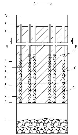
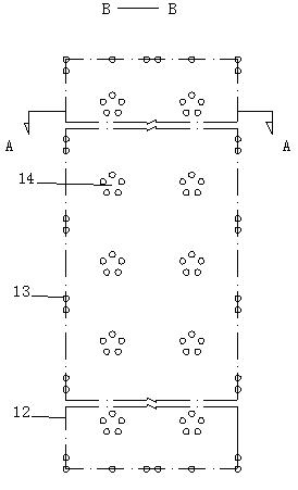
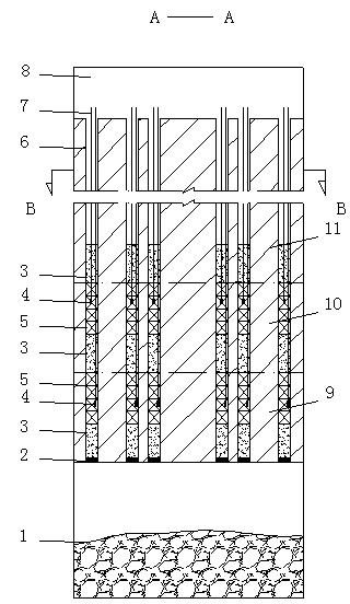
[0034] Lead-zinc ore: The thickness of the ore body is 20m, and the inclination angle is 75°, which is divided into ore blocks along the direction of the ore body. It is mined by the large-diameter deep hole open field and then filling mining method. The stope is 60m long and 20m wide; Ф165mm blastholes are used to blast vertically to drop ore, and the blasthole depth is 50m. The cluster holes in the mine house are composed of 5 blastholes, the distance between the blastholes in the beam is 0.86m, and the distance between the beams is 7.5m. Double boreholes with a spacing of 0.86m are arranged along the stope boundary, and the distance between the double boreholes is 7.5m, which are staggered from the cluster boreholes. The length of the upper, middle and lower layers of sand filling in the blast hole is all 4m, and the length of the upper and lower layers of explosive charge is 3.5m. Layer height 7.5m. The stope caving adopts two layers of caving at the same time, the deton...

Embodiment 2

[0036] XX Copper Mine: The thickness of the ore body is 30m, and the inclination angle is 35°. It is mined by the method of large-diameter deep hole open field and then filling. It is divided into ore blocks along the strike of the ore body. The width of the mine room is 12m, and the length of the mine room is 40m. Adopt Ф120mm blast hole to drop vertically deep blasting ore, and blast hole depth is 40m. The cluster hole in the mine room is composed of 8 blastholes, the distance between the blastholes in the beam is 0.5m, and the distance between the beams is 6.5m. The length of the upper, middle and lower layers of sand filling in the blast hole is all 3m, and the length of the upper and lower layers of explosive charge is 3.5m. Layer height 6.5m. The stope caving adopts two layers of caving at the same time, the detonation time of layered differential is 50 ms, and the height of one caving is 13m. Ф120mm blast holes per meter of blast holes can break 12t of ore, explosive...


PUM

PropertyMeasurementUnit
Heightaaaaaaaaaa

Abstract

The invention discloses a multilayer blasting method for bundle holes, comprising the following steps: a) 5-8 blast holes with the diameter of 120-165mm are opened in the middle of a stope; the annular bundle holes are composed by the blast holes, wherein the spacing in the bundle holes is 0.5-0.86m; the spacing of the bundle holes, namely the distance between the central points of two adjacent annular bundle holes, is 6.5-7.5m; dual holes with the spacing of 0.5-0.86m are arranged along the boundary of the stope; the spacing of the dual holes is 6.5-7.5m; the dual holes are staggered with the bundle holes; and each stopping plug is arranged at the bottom of each blast hole; b) each blast hole is divided into multiple layers; the height of each layer is 6.5-7.5m; fillers and dynamite are arranged in each layer from bottom to top; detonators are embedded in the dynamites, wherein the thickness of the filler is 3-4m; and c) the blast holes in the same layer are detonated simultaneously; differential spaced detonation is adopted between the layers with the differential time interval of 25-50ms. The multilayer blasting method for bundle holes is used for mining and has the advantages of solving the problem of frequent blasting during the delaminated mining process, shortening the mining cycle in the stope, and improving mining intensity.

Description

technical field [0001] The invention relates to the field of mining, in particular to a multi-layer blasting method for cluster holes. Background technique [0002] The most basic operation of mining operation is to break the whole ore into smaller ore blocks, so that the ore is separated from the bedrock, so that the ore can be extracted. The blasting method, as the most extensive and effective means of breaking rocks in metal ore mining at present, will still be the commonly used and most effective method of breaking hard to hard rocks in the foreseeable future. [0003] As a safe, efficient, low-cost and large-scale mining method in mining production, deep hole blasting mining is widely used in many low-grade mines and thick ore bodies. The high-stage large-diameter deep-hole mining method has reasonable stope structure, high drilling efficiency, advanced blasting technology, large amount of ore collapse at one time, concentrated and continuous ore output, high degree of...

Claims


Application Information

Patent Timeline
IPC IPC(8): F42D1/00F42D3/04
Inventor 陈何王湖鑫刘建东孙忠铭
Owner BEIJING GENERAL RES INST OF MINING & METALLURGY
Learn More