Acoustic resonator

A technology of acoustic wave resonator and acoustic isolator, which is applied in the direction of electrical components, impedance networks, etc., can solve the problems such as the increase of ripple coefficient in the passband of the filter, and achieve the effect of avoiding electromechanical coupling coefficient, easy implementation, and high quality factor

Active Publication Date: 2011-10-19
张浩
View PDF3 Cites 11 Cited by
  • Summary
  • Abstract
  • Description
  • Claims
  • Application Information

AI Technical Summary

Problems solved by technology

At the same time, the spurious mode will cause an increase in the ripple coefficient in the passband of the filter

Method used


Image

  • Acoustic resonator
  • Acoustic resonator
  • Acoustic resonator

Examples


Embodiment Construction

[0058] The acoustic wave resonator of the present invention will be described in detail below with reference to the embodiments and the accompanying drawings.

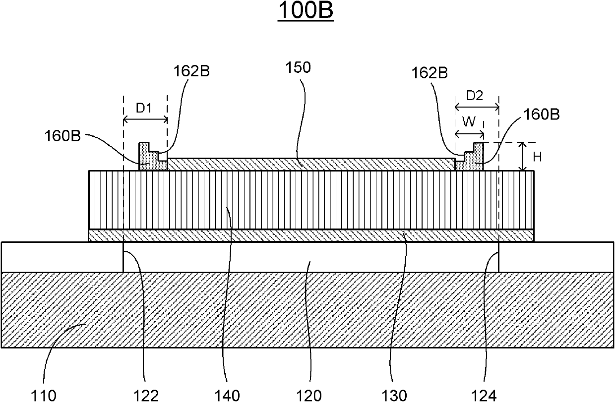
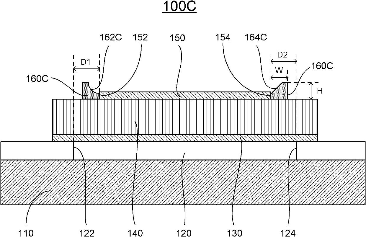
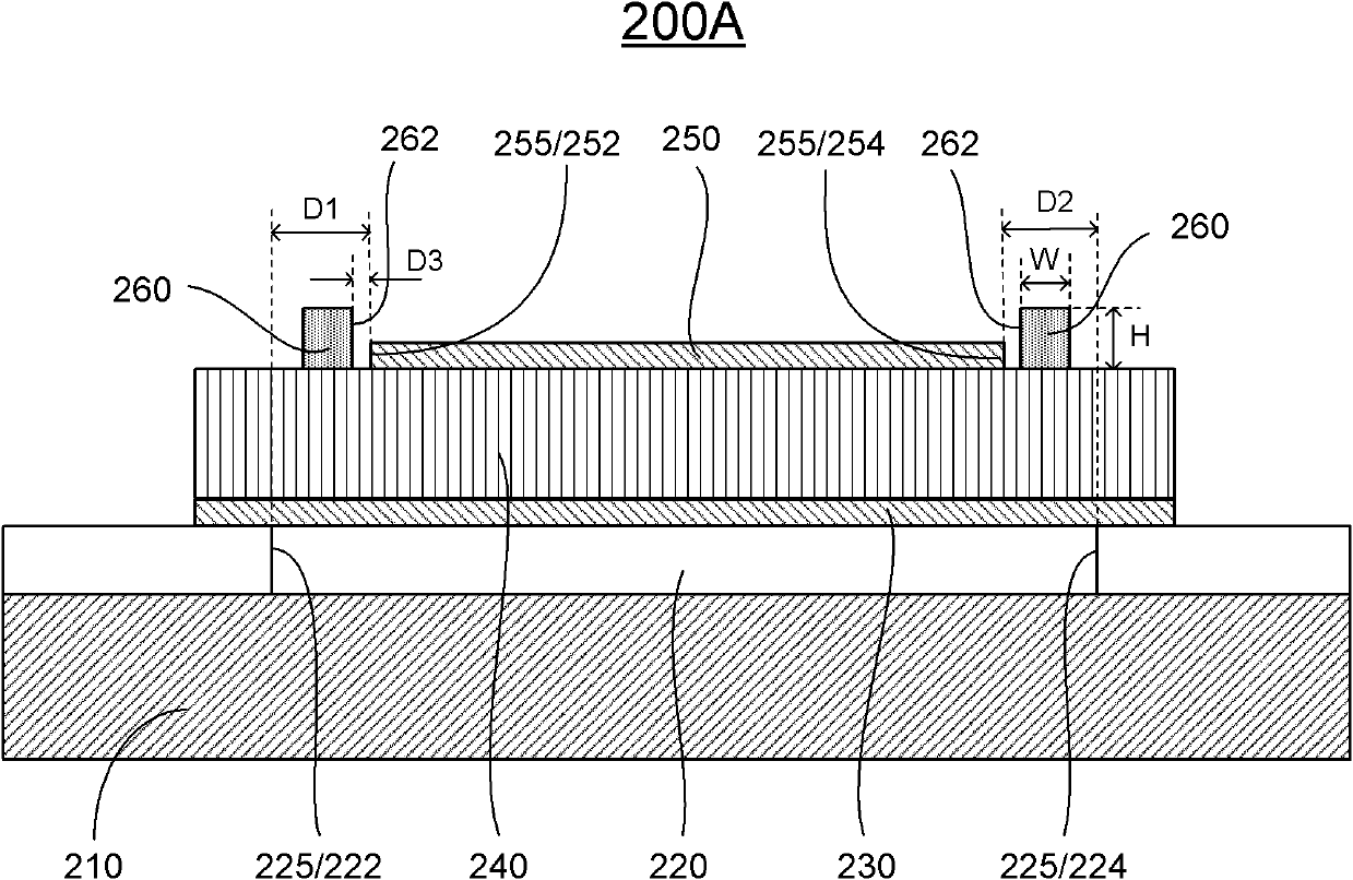
[0059] The specific implementation forms of the present invention are described together with the description and the accompanying drawings. According to the purpose of the present invention, the specific implementation forms of the present invention are generally described here, and on the one hand, the patent will be described in more detail below with reference to the accompanying drawings. In accordance with the purpose of the present invention, as previously discussed in detail, the present invention relates to acoustic wave resonators / devices whose electrical characteristics are enhanced by applying boundary loads such as padding around top or bottom electrodes.

[0060] An acoustic wave resonator includes a substrate, an acoustic isolator formed in or on the substrate, a first (bottom) electrode formed on the ac...


PUM


Abstract

The invention discloses an acoustic resonator, comprising a substrate, a sound isolator formed in or above the substrate, a first electrode formed on the sound isolator, a piezoelectric layer formed on the first electrode, a second electrode formed on the piezoelectric layer, and a liner formed on the piezoelectric layer, wherein one end of an edge of the sound isolator is defined as a first boundary while the other end is defined as a second boundary, one end of an edge of the second electrode is defined as a first boundary while the other end is defined as a second boundary, and the edge of the second electrode is positioned at inner side of the edge of the sound isolator, and the liner surrounds the edge of the second electrode and is positioned at the inner side of the edge of the sound isolator. The acoustic resonator disclosed by the invention is simple in structure and easy for implementation and has a higher quantization parameter (Qp). Furthermore, the acoustic resonator cannot damage the quality standard (Qs) and an effective electromechanical coupling coefficient and can avoid a parasitic mode.

Description

technical field [0001] The present invention relates to an acoustic wave device, in particular to a piezoelectric thin film bulk acoustic wave resonator whose electrical performance is improved by applying a boundary load, such as adding pads at the top or bottom electrode boundary. Background technique [0002] Mobile communication products, such as mobile phones and handheld devices, are rapidly developing towards miniaturization and portability. Such products require radio frequency (RF) filters covering the frequency range roughly 0.5 GHz to 10 GHz to protect the received signal from interference, which may come from a transmitter in the same handheld device or from noise formed outside the device Signal. This requires that the filter must have a low passband insertion loss (usually less than 2dB) to achieve a suitable signal-to-noise ratio. Thin-film bulk acoustic wave (BAW) resonators and filters are widely used in wireless mobile communication devices due to their h...

Claims


Application Information

Patent Timeline
Patent Type & Authority Applications(China)
IPC IPC(8): H03H9/17
Inventor 张浩庞慰
Owner 张浩
Why Eureka
Try Eureka