Compound heat exchange unit

A technology of heat exchangers and water-cooled heat exchangers, applied in the direction of heat exchanger types, heat exchanger shells, indirect heat exchangers, etc., can solve the problems of cooling system performance degradation, reliability degradation, and heat exchange efficiency degradation. Achieve the effect of improving lubricating oil retention, improving heat transfer efficiency, and retention suppression effect

Inactive Publication Date: 2011-10-19
CALSONIC KANSEI CORP
View PDF3 Cites 12 Cited by
  • Summary
  • Abstract
  • Description
  • Claims
  • Application Information

AI Technical Summary

Problems solved by technology

When the lubricating oil stays, there is a concern that the performance and reliability of the cooling system will decrease due to a decrease in heat exchange efficiency and insufficient lubrication of the compressor.

Method used


Image

  • Compound heat exchange unit
  • Compound heat exchange unit
  • Compound heat exchange unit

Examples


no. 1 Embodiment approach

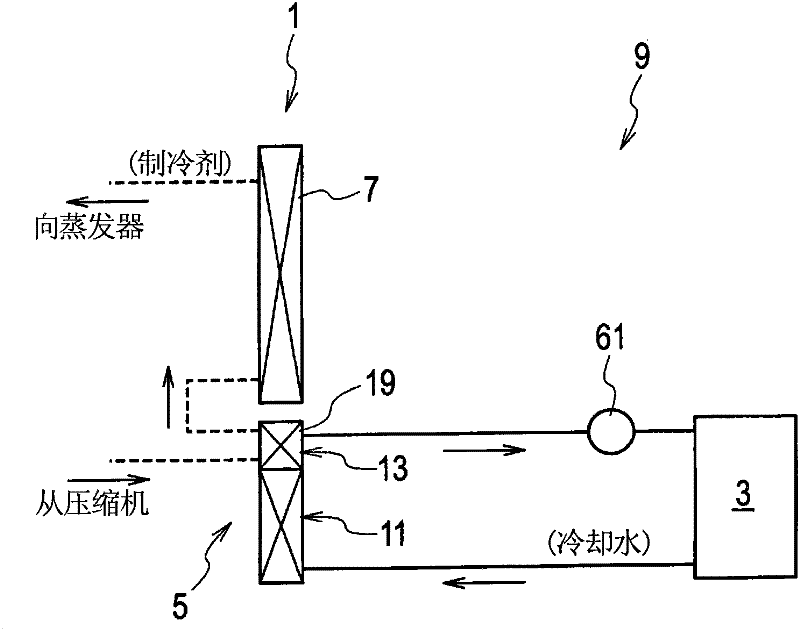
[0037] refer to Figure 1 to Figure 7 The composite heat exchanger 1 of the first embodiment will be described. Such as figure 1 As shown, the composite heat exchanger 1 is used in a cooling system 9 of a hybrid electric vehicle using an engine (internal combustion engine: not shown) and an electric motor 3 as driving power sources.

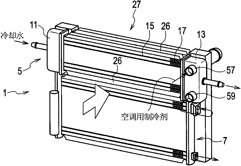
[0038] Such as figure 1 As shown, the composite heat exchanger 1 is used in a cooling system 9 having an auxiliary radiator 5 (first air-cooled heat exchanger) and a condenser 7 (second air-cooled heat exchanger). The auxiliary radiator 5 is used for cooling cooling water for control devices (heat generating elements other than the engine) such as the drive motor 3 and an inverter (inverter) and a frequency converter (converter). On the other hand, the condenser 7 is used to cool the refrigerant for cabin air conditioning.

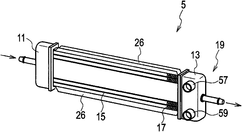
[0039] Such as Figure 1 ~ Figure 3 As shown, the auxiliary radiator 5 has an upstream tank 11 , a downstream tank 1...

no. 2 Embodiment approach

[0057] refer to Figure 8 (a) and Figure 8 (b) explains the compound heat exchanger of 2nd Embodiment.

[0058] In the composite heat exchanger of this embodiment, the inner fins (refrigerant flow unit) 101 fixed inside the outer shell tube (refrigerant flow channel unit) 21 are extended to the two ends of the outer shell tube 21 in the refrigerant flow direction. arc part. Furthermore, a pair of slits 103 extending from the inflow hole 51 are provided on both sides of the inflow hole 51 . Likewise, a pair of slits 105 extending from the outflow hole 53 are provided on both sides of the outflow hole 53 . The inner fins 101 and the outer shell tube 21 are brazed at the tops of the waves of the inner fins 101 and at both ends in the flow direction of the refrigerant. Therefore, it is possible to ensure the pressure resistance of the tube to both ends in the flow direction.

[0059] Slits 103 , 105 are provided across several slots 55 . By the slits 103 and 105, the refrig...

no. 3 Embodiment approach

[0063] refer to Figure 9 (a) and Figure 9 (b) explains the compound heat exchanger of 3rd Embodiment.

[0064] In the compound heat exchanger of this embodiment, notches 153 and 155 are provided on the inner fins (refrigerant flow path unit) 151 . Along the end portion 157 ( Figure 4 ), an upper notch 153 is provided in the width direction. Similarly, along the end portion 159 ( Figure 4 ), a notch 155 below is provided in the width direction.

[0065] Notches 153 , 155 are provided across the entire slot 55 . The notches 153 and 155 allow the refrigerant to diffuse (from the inflow hole 51 to the notch 153 ) or concentrate (from the notch 155 to the outflow hole 53 ) in a direction (width direction) substantially perpendicular to the flow direction thereof. The notches 153 and 155 are used to make the refrigerant flow across the entire width of the shell tube 21 , thus enlarging the contact area between the refrigerant and the cooling water and improving the heat ex...


PUM


Abstract

Disclosed is a compound heat exchange unit equipped with a first air-cooled heat exchange unit (5) that cools cooling water for the heat-generating body of an automobile other than the internal combustion engine and a second air-cooled heat exchanger unit that cools a coolant for vehicle air conditioning. The first air-cooled heat exchange unit comprises an upstream tank into which cooling water flows, a downstream tank from which coolant flows, a flow path member that connects the upstream tank to the downstream tank, radiator fins which are layered alternately with the flow path member, and a water-cooled heat exchange unit that cools the coolant. The water-cooled heat exchange unit is disposed within the downstream tank; at the upper part thereof there is an inlet port into which the coolant flows, and at the lower part thereof there is an outlet port from which the coolant flows. By means of the aforementioned heat exchange unit, it is possible to prevent accumulation of oil mixed with the coolant, heat exchange efficiency can be improved, and reduced size can be achieved.

Description

technical field [0001] The present invention relates to a combined heat exchanger using plural kinds of refrigerants such as engine cooling water and refrigerants for air conditioners in a cooling system for automobiles. Background technique [0002] A heat exchanger is disclosed in JP 2006-162176 A (Patent Document 1). [0003] This heat exchanger is used in an air conditioner for a vehicle, and the heat exchanger for the air-conditioning refrigerant is assembled in the tank (tank) (header) of the air-cooled heat exchanger for engine cooling water, and the air-cooled Cooling water to cool the refrigerant used in the air conditioner. In this refrigerant heat exchanger, refrigerant flows in from below and flows out from above. [0004] Lubricating oil of a compressor (compressor) is mixed in the refrigerant for air conditioners, and the refrigerant circulates in the system together with the mixed lubricating oil. A part of the mixed lubricating oil is separated from the re...

Claims


Application Information

Patent Timeline
Patent Type & Authority Applications(China)
IPC IPC(8): F28F9/02F28F9/26
CPCF28D1/0452F28F9/0234
Inventor 岩崎充回谷雄一
Owner CALSONIC KANSEI CORP
Why Eureka
Try Eureka