Vertical sieve plate used for fluidized bed
A vertical sieve plate, fluidized bed technology, applied in the field of internal components, to achieve the effect of large processing capacity, small fluctuation of bed pressure drop, and many contact opportunities
- Summary
- Abstract
- Description
- Claims
- Application Information
AI Technical Summary
Problems solved by technology
Method used
Image
Examples
Embodiment 1
[0015] Vertical sieve plate component with one cap:
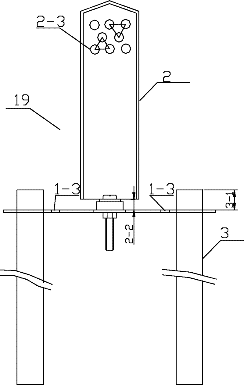
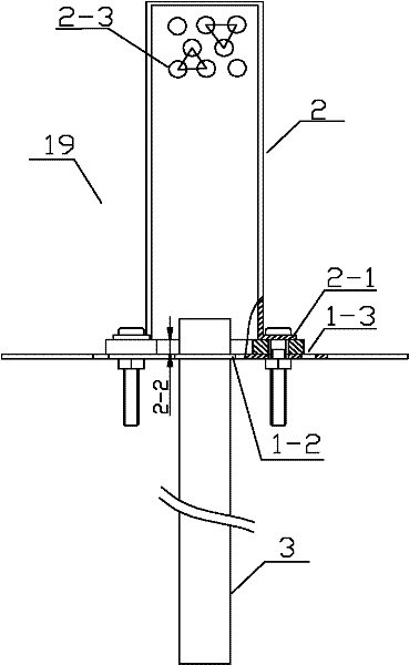
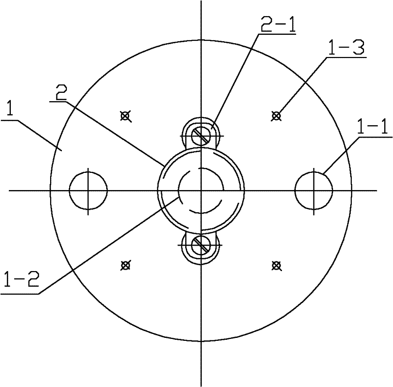
[0016] The vertical screen member 19 is the core component of the fluidized bed. When the size of the fluidized bed is small, its structure is determined by figure 1 Combine figure 2 and image 3 As shown, it includes a circular support plate 1, a cap 2 and an overflow pipe 3. The diameter of the support plate 1 is larger than the inner diameter of the fluidized bed; there are two symmetrical overflow pipe holes 1 in the radial direction of the support plate 1. 1. The center distance between the two overflow pipe holes is 0.52-0.86 of the inner diameter of the fluidized bed; the support plate 1 is provided with a circular plate hole 1-2 concentric with it, and the circular plate hole 1-2 is connected to the support plate 1. The diameter ratio is 0.19-0.28, the best value is 0.25; four solid fluidization holes 1-3 are evenly distributed on the support plate 1, and the diameter ratio of the solid fluidization holes 1-3 to the c...
Embodiment 2
[0023] Vertical sieve components with multiple caps:
[0024] When the size of the fluidized bed is large, the number of caps 2 and plate holes 1-2 on the support plate 1 can be one or more, and the specific number n is determined by the cross-sectional area of the support plate A and cap 2 in the fluidized bed. Diameter, initial fluidization velocity u mf And the air velocity u of the circular plate hole 1-2 i Determine, meet the formula u mf A=nu i A i , Where A i Is the area of each circular plate hole 1-2. The circular plate holes 1-2 and the cap 2 are evenly distributed on the support plate 1, and the distance between the centers of two adjacent circular plate holes 1-2 should meet the following conditions: The gas-solid separation holes on the adjacent cap 2 2-3 The ejection curve of the ejected solid particles just meet or tangent at the midpoint of the distance. The principle of the arrangement of the plate holes 1-2 and the cap 2 on the support plate is to ensure tha...
PUM
 Abstract
Description
Claims
Application Information
 - R&D
- Intellectual Property
- Life Sciences
- Materials
- Tech Scout
- Unparalleled Data Quality
- Higher Quality Content
- 60% Fewer Hallucinations
Browse by: Latest US Patents, China's latest patents, Technical Efficacy Thesaurus, Application Domain, Technology Topic, Popular Technical Reports.
© 2025 PatSnap. All rights reserved.Legal|Privacy policy|Modern Slavery Act Transparency Statement|Sitemap|About US| Contact US: help@patsnap.com


