Co-rotating outflow internal-hole type high performance swirling separator

A cyclone separator, a high-efficiency technology, applied in the direction of the cyclone device, the device whose axial direction of the cyclone remains unchanged, etc., can solve the problems such as difficulty in meeting the water injection requirements, low oil removal efficiency in the settling section, and increased load on the filtration section , to achieve the effect of flexible and convenient process installation, improved treatment effect and improved deoiling efficiency

Inactive Publication Date: 2011-10-26
NORTHEAST GASOLINEEUM UNIV
View PDF9 Cites 15 Cited by
  • Summary
  • Abstract
  • Description
  • Claims
  • Application Information

AI Technical Summary

Problems solved by technology

Due to the high viscosity of the polymer-containing sewage, the oil removal efficiency of the subsidence section in the oil field surface process is low, which increases the load of the filter section, resulting in serious pollution of the filter materi

Method used


Image

  • Co-rotating outflow internal-hole type high performance swirling separator
  • Co-rotating outflow internal-hole type high performance swirling separator
  • Co-rotating outflow internal-hole type high performance swirling separator

Examples


Embodiment Construction

[0011] The present invention will be further described below in conjunction with accompanying drawing:

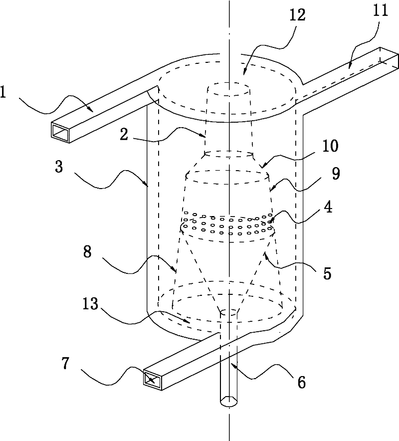
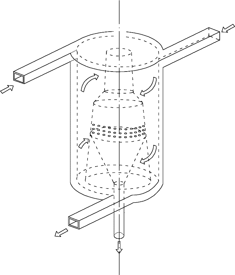
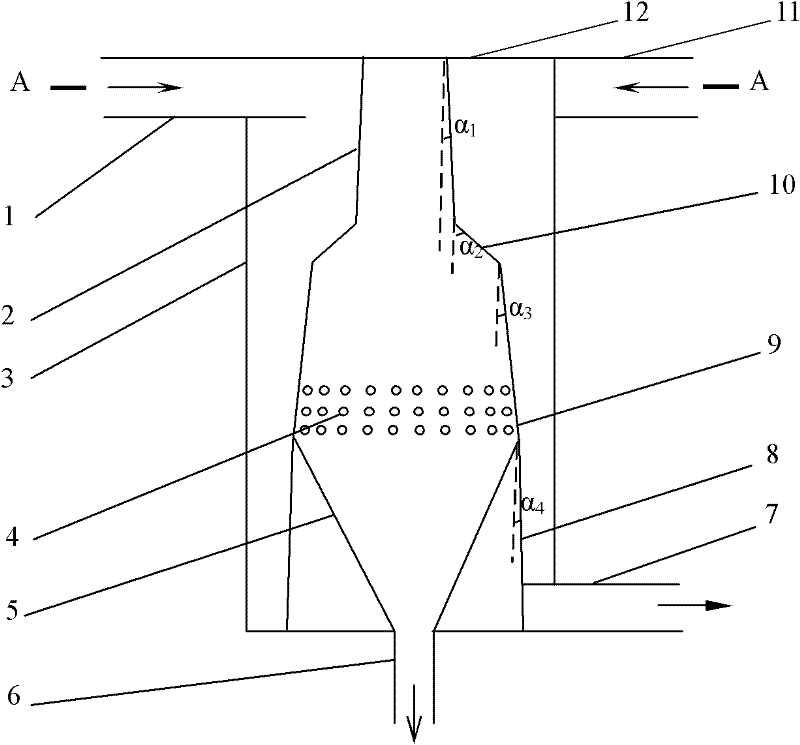
[0012] This kind of high-efficiency cyclone separator with internal holes flowing in the same direction has a structure such as figure 1 combine image 3 , Figure 4 As shown, it includes the No. 1 inlet pipe 1 of the swirl flow, the No. 2 inlet pipe 11 of the swirl flow, the cylindrical outer swirl fluid 3 located on the same horizontal plane, and the upper sealing surface 12 and the Conventional structures such as the lower closed surface 13 are unique in that:

[0013] Between the upper and lower sealing surfaces, there is fixed a swirl cavity section inner cylinder 2, a large cone section inner cylinder 10, a small cone section inner cylinder 9 and a tailpipe section inner cylinder 8 which are sequentially connected from top to bottom. Conical multi-stage internal swirl fluid, the cavity formed between the inner wall of the outer swirl fluid 3 and the outer wall of t...


PUM

PropertyMeasurementUnit
Angleaaaaaaaaaa
Angleaaaaaaaaaa
Angleaaaaaaaaaa

Abstract

The invention discloses a co-rotating outflow internal-hole type high performance swirling separator. In the prior art, an effect of removal of fine oil drop of hydroclone is poor. According to the swirling separator, a problem of the prior art is solved. The swirling separator is characterized in that: a circular table-shaped multi-stage internal swirling body is fixed between an upper sealing surface and a lower sealing surface, wherein a inner cylinder in the swirling chamber portion, a inner cylinder in the large conoid portion, a inner cylinder in the small conoid portion, and a inner cylinder in the tail tube portion are sequentially connected from the top to the bottom to form the circular table-shaped multi-stage internal swirling body; the inner cylinder in the small conoid portion has a hollow structure, and is provided with oil collecting holes; a funnel-shaped oil collecting cone is arranged in the inner cylinder in the tail tube portion, an upper open of the oil collecting cone is communicated with the inner chamber of the inner cylinder in the small conoid portion, and a lower open of the collecting cone passes through the center of the lower sealing surface, and forms a fixed connection with a oil output tube, wherein the oil output tube is introduced vertically; a water output tube is connected to the bottom of a outer swirling body, wherein the water output tube is introduced along tangent line direction to the circle of the outer swirling body and is communicated with a swirling inner chamber, swirling water output direction of the water output tube is the same as the swirling direction in the swirling inner chamber. The swirling separator has characteristics of removal of the tiny oil drop in the water, high separation efficiency and simple structure.

Description

technical field [0001] The invention relates to a liquid-liquid two-phase separation device applicable in the fields of petrochemical industry and environmental protection, in particular to a hydrocyclone. Background technique [0002] At present, the rapid separation methods used for two-phase (oil-water two-phase as an example) mainly include cyclone separation, air flotation, filtration and membrane separation. Cyclone separation has the advantages of small equipment size, but its ability to remove small oil droplets is limited; air flotation can adapt to a small range of oil concentration changes; However, frequent backwashing is required to ensure the long-term stable operation of the equipment; the cost of membrane separation equipment is relatively high, and the requirements for medium conditions are relatively strict. The separation principle of the hydrocyclone is to use the density difference between the media to carry out centrifugal separation. The larger the de...

Claims


Application Information

Patent Timeline
IPC IPC(8): B04C3/00
Inventor 刘扬赵立新蒋明虎李枫
Owner NORTHEAST GASOLINEEUM UNIV
Why Eureka
Try Eureka