Turbine power generating system by utilizing wind from train travelling

A technology of power generation system and wind power generator, applied in the direction of wind power generator at right angles to the wind direction, wind power motor, wind power motor combination, etc., can solve the problems of voltage value fluctuation, large output voltage fluctuation, and shortened service life, and achieve structural Simple and reasonable, improved reliability, large torque effect

Inactive Publication Date: 2011-10-26
孔慧
View PDF5 Cites 2 Cited by
  • Summary
  • Abstract
  • Description
  • Claims
  • Application Information

AI Technical Summary

Problems solved by technology

[0008] In addition, after the train passed by, due to the large fluctuations in the driving wind, the impeller and the speed of the wind turbine had severe impacts, which not only caused fluctuations in the generated voltage value, but also caused damage to the wind turbine device in severe cases.
Usually, a simple clutch device is used to disconnect the impeller from the generator. Although this method avoids damage to the motor due to overspeed, the output voltage also fluctuates greatly. At the same time, the impeller of the wind turbine is often running at high speed due to light load. Afterwards, the service life is greatly reduced, which in turn affects the entire system

Method used


Image

  • Turbine power generating system by utilizing wind from train travelling
  • Turbine power generating system by utilizing wind from train travelling
  • Turbine power generating system by utilizing wind from train travelling

Examples


Embodiment Construction

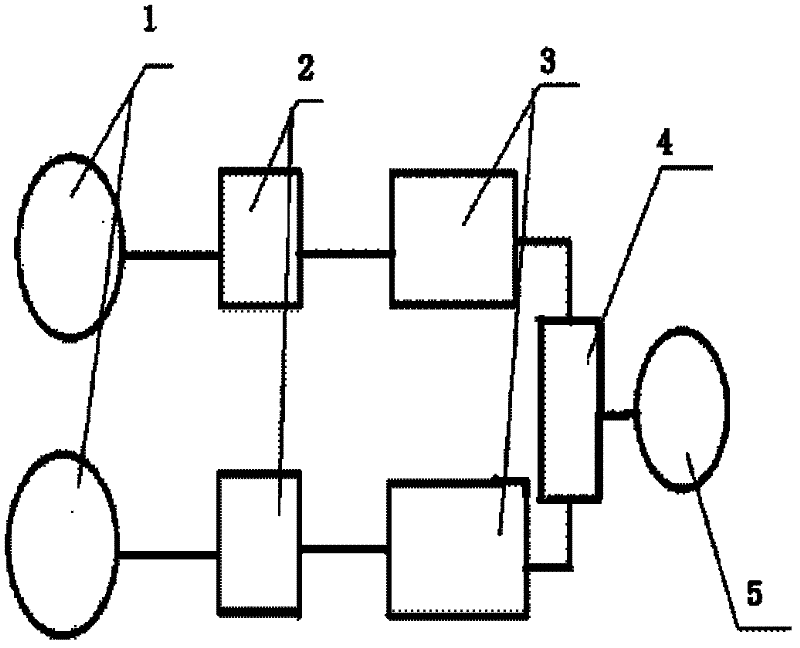
[0027] figure 1 The schematic diagram of the overall scheme of the Nakamoto system takes a group of power generation units on both sides of the road as an example. The power generation units include wind turbine 1, controller 2, and battery pack 3; The controller 2 is electrically connected; the controller 2 is electrically connected to the battery pack 3; each battery pack 3 is electrically connected to the power distribution device 4; the power distribution device 4 is electrically connected to the load 5.

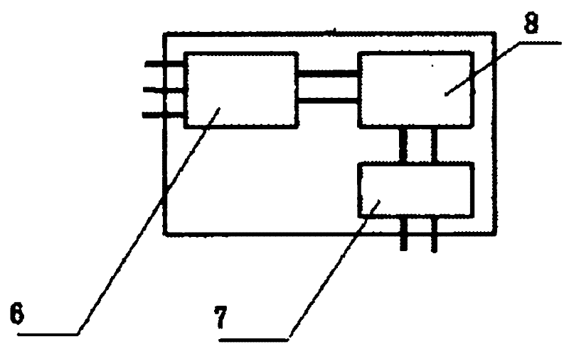
[0028] figure 2 The middle is a schematic diagram of the electrical and control parts. In the figure, the rectifier 6, the chopper 7 and the charger 8 are electrically connected in sequence.

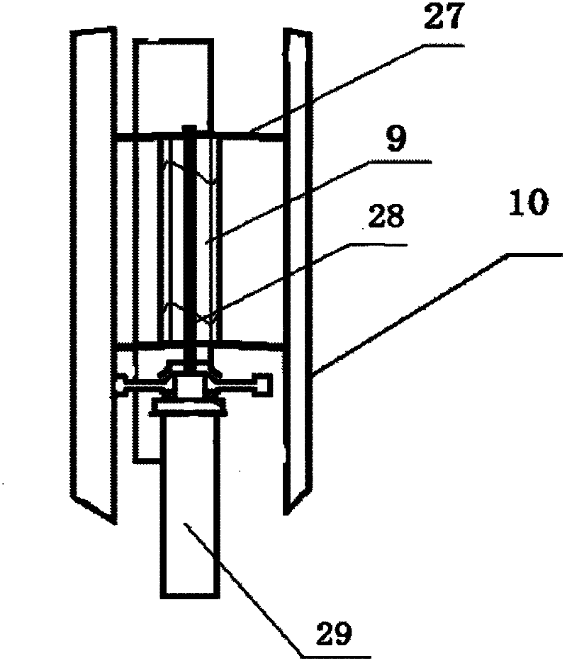
[0029] image 3 It is a structural schematic diagram of a vertical-axis wind-driven generator. The shaft 28 of the vertical-axis wind-driven generator 1 is in the vertical direction, and the shaft 28 is provided with an S-shaped wind wheel 9, an H-shaped wind wheel 10, and a fl...


PUM


Abstract

The invention provides a turbine power generating system by utilizing wind from train travelling. Because of the effect of the wind from train travelling, the output voltage has greater waves, further influences are leaded to the whole system; at least one power generating unit is arranged at two sides of the road for the train by the system, a vertical axial wind-driven power generator in each power generating unit is electrically connected with a controller, and the controller is electrically connected with a battery set; the battery set in each power generating unit is electrically connected with a power distribution device; and the power distribution device is electrically connected with loads. By adopting the scheme for combining an S-shaped wind wheel and an H-shaped wind wheel, andthe optimal performance match of a fan is achieved; and additionally, a vertical axial wind-driven power generator rotor is provided with a flywheel clutch device, through detecting the changes of the rotation speed of the wind-driven power generator, signals are sent to a feedback controller, the feedback controller analyzes and decides whether instructions are sent to an electromagnetic actuation unit to load the flywheel to rotate or unload the flywheel to rotate, thus the rotation speed is ensured to stable, and the system works normally.

Description

technical field [0001] The invention relates to a turbine power generation system utilizing train running wind. Background technique [0002] With the development of my country's economy, a large number of electrified railways such as the Beijing-Shanghai high-speed railway have been put into use, marking that my country's railways have entered the era of high-speed railways. With the rapid development of railway construction, more and more electric energy is consumed in railway supporting facilities. A specially designed vertical axis wind turbine is used to collect and generate electricity from the driving wind energy generated after the high-speed train runs. According to research, trains need to overcome aerodynamic resistance to move forward when they are running. The front of the train will occupy the original air position, squeeze the air around the body, and there is a nearly vacuum space at the rear of the train. The huge difference in air density will cause the ...

Claims


Application Information

Patent Timeline
Patent Type & Authority Applications(China)
IPC IPC(8): F03D9/00F03D3/00H02J7/00H02K7/10
CPCY02E10/74
Inventor 孔慧黄俊炜
Owner 孔慧
Why Eureka
Try Eureka