Supercharge Your Innovation With Domain-Expert AI Agents!

ACF attachment device and display device manufacturing method

A technology for pasting devices and manufacturing methods, which is applied in the fields of identification devices, printed circuit manufacturing, semiconductor/solid-state device manufacturing, etc. It can solve the problems of easy sliding of ACF tapes, lower equipment operation rate, and error adjustment of ACF tapes, and achieve beautiful end face shape , reduced auxiliary material costs, positional accuracy and high-quality results

Active Publication Date: 2014-11-05
NEC LCD TECH CORP
View PDF6 Cites 0 Cited by
  • Summary
  • Abstract
  • Description
  • Claims
  • Application Information

AI Technical Summary

Problems solved by technology

[0013] and, if Figure 9 As shown in the "unqualified situation" of , when a part of the unnecessary ACF part 197 is attached to the lower clamping part 111, and the clamping clamping part 109 is opened, the ACF belt 199 is stretched and clamped The drive shaft of the clamping member 109 is overloaded, and the drive shaft overload abnormality causes the device to stop abnormally. As a result, the operation rate of the equipment is reduced.
[0014] 2) The second shortcoming of the existing ACF pasting device is that in the action of 1), the unnecessary ACF portion 197 remaining on the ACF tape 199 is attached to the lower clamping member 111, and the lower clamping member 111 and the unnecessary In the state where a part of the ACF portion 197 is attached, the clip 109 is clamped and opened, and the ACF tape 199 is stretched, and the panel-attached ACF portion 198 that should have remained on the spacer 103 is also clamped by the clip. 109 was stretched and peeled off, and it was not attached to the correct position of the liquid crystal panel 112. As a result, the product with poor ACF adhesion was rejected
In addition, when the peeled panel ACF portion 198 is pasted on the clamping member 109 and its peripheral equipment, problems as described in 1) will occur.
[0015] 3) The third shortcoming of the existing ACF sticking device is that in the action of 1), the unnecessary ACF portion 197 remaining on the ACF tape 199 is attached to the lower clamping member 111, and the unnecessary ACF portion 197 remaining on the ACF tape 199 is attached to the lower clamping member 111. In the state where a part of the ACF portion 197 is attached, the clamping and clamping member 109 is opened, and the ACF tape 199 is stretched, and the panel-attached ACF portion 198 that should have remained on the spacer 103 is also clamped and clamped. Piece 109 is stretched under tension while peeling
[0016] When the ACF scraps of the peeled-off panel pasting ACF portion 198 are pasted on the equipment of the device, the problem described in 2) above will occur, but when pasted on the display area of ​​the liquid crystal panel 112, it will become When the liquid crystal display device is turned on and displayed, the part where ACF chips are attached cannot be displayed normally, and it becomes a product failure (display failure)
The unqualified liquid crystal display device can be made into a qualified part by disassembling and removing the repair work of ACF chips attached to the liquid crystal panel, but the repair work has the problems of consuming man-hours and affecting the yield rate.
[0017] 4) Disadvantage of Patent Document 2 (Japanese Patent Laid-Open No. 9-6251). In the case where the ACF tape is drawn out by using a clip, sufficient biting is required in order to pull out the ACF tape without slipping.
In the state where the ACF tape is fully bitten by the clip, it may not be easy to separate due to the adhesive force of the ACF part, and the problem that the ACF part is difficult to peel off from the clip by blowing air alone cannot be avoided.
In addition, when adjusting by reducing the biting amount of the clip to such an extent that the ACF portion can be peeled off from the clip by blowing air, the ACF band may be easily slipped, and it is necessary to determine the optimal biting amount each time. , there is no way to avoid the need for error adjustment for each ACF band

Method used


Image

  • ACF attachment device and display device manufacturing method
  • ACF attachment device and display device manufacturing method
  • ACF attachment device and display device manufacturing method

Examples


Embodiment 1

[0043] In order to further describe the above-mentioned embodiments of the present invention in detail, refer to figure 1 and figure 2 A first embodiment of the present invention will be described.

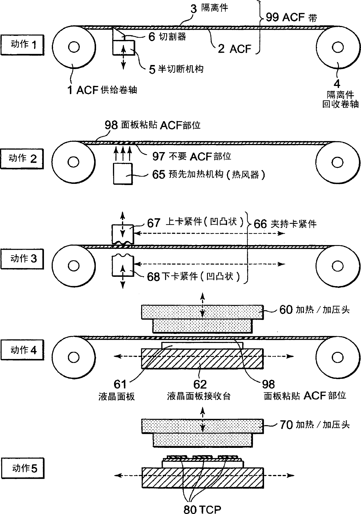
[0044] like figure 1 As shown, the ACF pasting device of this embodiment at least includes: ACF supply reel 1, spacer recovery reel 4, half-cut mechanism 5, preheating mechanism 65, clamping and clamping member 66, heating / pressurizing head 60, liquid crystal panel receiving station 62 . In addition, the ACF tape 99 is generally composed of a double-layer structure of the ACF 2 and the cover film called the spacer 3 .

[0045] Next, the operation of the ACF pasting device of the embodiment will be described.

[0046] In "Operation 1", first, the cutter 6 of the half-cutting mechanism 5 half-cuts the ACF tape 99 that imparts thermosetting properties and integrates the ACF 2 and the separator 3 .

[0047] The half cutting is performed by bringing the cutter 6 into contact wi...

Embodiment 2

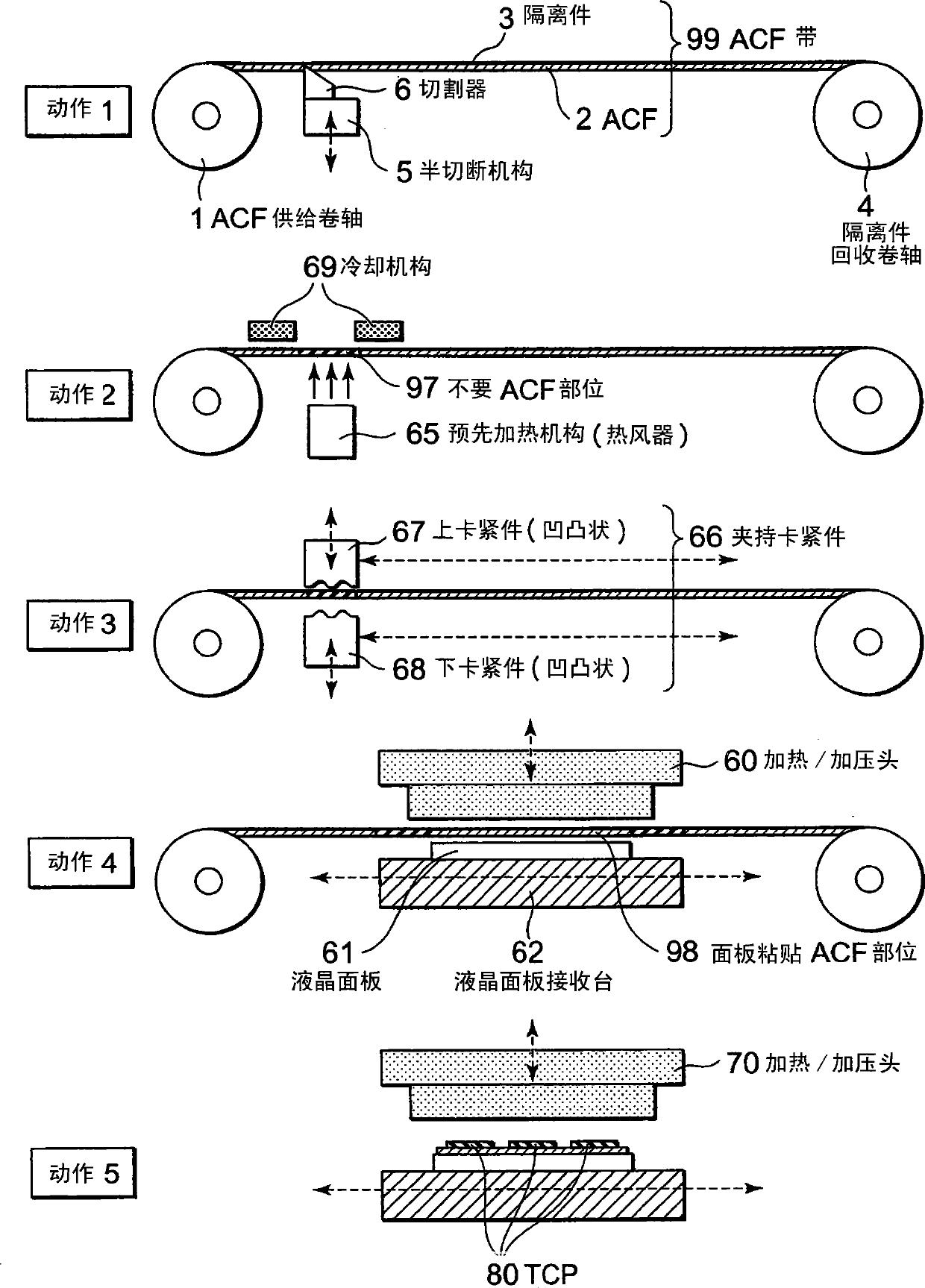
[0074] Second, refer to image 3 A second embodiment of the present invention will be described.

[0075] The basic structure of the ACF pasting device of this embodiment is the same as that of Embodiment 1, but as image 3 As shown in "Action 2" of , the difference from the first embodiment is that a cooling mechanism 69 is provided in order to suppress the hardening of the panel bonding ACF portion 98 adjacent to the unnecessary ACF portion 97 . Hereinafter, this difference will be described.

[0076] In this embodiment, before the heater of the preheating mechanism 65 is turned on, the cooling mechanism 69 is lowered so that the spacer 3 at the ACF portion 98 of the panel is in contact with the cooling mechanism 69 . Accordingly, it is possible to suppress the heating of the panel bonding ACF portion 98 .

[0077] After the unnecessary ACF portion 97 is cured, the preheating mechanism 65 is turned off to stop blowing of warm air, and the cooling mechanism 69 is further r...

Embodiment 3

[0081] Second, refer to Figure 4 A third embodiment of the present invention will be described.

[0082] In this example, if Figure 4 As shown in "Action 2", the cooling mechanism 69 is provided in order to prevent the hardening of the panel-attached ACF portion 98 adjacent to the unnecessary ACF portion 97. The contact heater is different in that the unnecessary ACF portion 97 is removed by the belt recovery mechanism 57 before the ACF belt 99 is clamped by the clamping member 66 .

[0083] The difference will be described below.

[0084] like Figure 4 As shown in “Action 2 ”, after aligning the unnecessary ACF portion 97 of the ACF belt 99 with the preheating mechanism 64 , the preheating mechanism 64 is raised toward the unnecessary ACF portion 97 . At this time, the tape supply mechanism 56 and the tape recovery mechanism 57 are interlocked, and the tape 55 positioned between the preheating mechanism 64 and the ACF tape 99 is raised while being supported by the preh...


PUM


Abstract

Disclosed is an ACF attachment device capable of solving the problem occurring when a clamping chuck moves with an unnecessary ACF region adhering thereto; further disclosed is a display device manufacturing method. This ACF attachment device comprises: an ACF tape comprised of an ACF attached to a separator; a mechanism which moves the ACF tape; an alignment mechanism which controls the movement position of the ACF tape; a mechanism which cuts a portion of the ACF tape; a clamping chuck mechanism which clamps the ACF tape; a panel pedestal on which a display panel can be placed; and a heating / pressing head which is capable of making contact with the separator of the ACF tape; and heats the ACF tape being clamped by the heating / pressing head and the display panel placed on the panel pedestal to transfer the ACF to the display panel. In addition, this ACF attachment device is provided with a means which changes the adhesive property of a portion of the ACF before the ACF tape is clamped by the clamping mechanism.

Description

technical field [0001] The present invention relates to a device for pasting an anisotropic conductive film tape (hereinafter referred to as ACF (Anisotropic Conductive Film) tape) on a display panel and a method for manufacturing a display device using the same. Background technique [0002] like Figure 9 As shown, the existing ACF pasting device includes: ACF supply reel 101, spacer recovery reel 104, half-cut mechanism 105, peeling roller 107, clamping and clamping member 109, liquid crystal panel receiving platform 113, heating / pressurizing head 114 . [0003] refer to Figure 9 The pasting operation using such a conventional ACF pasting device will be described. [0004] First, in "Operation 1", the boundary between the unnecessary ACF part 197 that is not pasted on the liquid crystal panel by the cutter 106 of the half-cutting mechanism 105 and the panel pasting ACF part 198 that is pasted on the liquid crystal panel forms two parts. incision. [0005] In "Operatio...

Claims


Application Information

Patent Timeline
Patent Type & Authority Patents(China)
IPC IPC(8): G09F9/00G02F1/13G02F1/1345H01L21/60H05K3/32
CPCH05K2203/066H05K3/323H05K2203/1105H05K2203/0195G02F1/13G02F1/1345H05K3/32
Inventor 长谷川雄一
Owner NEC LCD TECH CORP
Features
  • R&D
  • Intellectual Property
  • Life Sciences
  • Materials
  • Tech Scout
  • Unparalleled Data Quality
  • Higher Quality Content
  • 60% Fewer Hallucinations
Learn More