Resin pipe joint
A resin tube and synthetic resin technology, applied in the direction of pipe joints, pipes/pipe joints/pipe fittings, pipeline connection layout, etc., can solve the problems of inability to visually confirm, difficult to confirm with the naked eye, etc., and achieve good assembly workability and good handling. Effect
- Summary
- Abstract
- Description
- Claims
- Application Information
AI Technical Summary
Problems solved by technology
Method used
Image

Examples
no. 1 example 〕
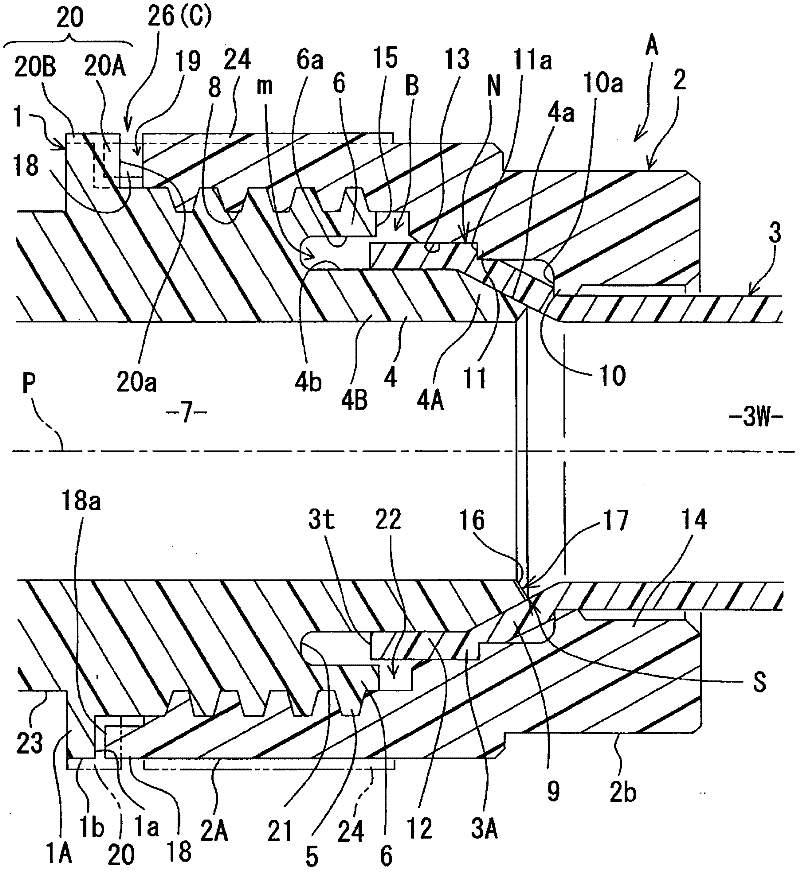
[0048] Such as figure 1 As shown, the resin pipe joint A of the first embodiment is used to connect the pipe 3 made of fluororesin (an example of synthetic resin represented by PFA, PTFE, etc.) Equal pipes are communicated and connected, and the joint main body 1 made of fluororesin (an example of synthetic resin represented by PFA, PTFE, etc.) and fluororesin (an example of synthetic resin represented by PFA, PTFE, etc.) Made of these two components of the union nut 2. also, figure 1 The tightening completed state (assembled state) after the union nut 2 has been screwed in by a predetermined amount is shown.
[0049] Such as figure 1 , figure 2 , Figure 4 As shown, the joint main body 1 is formed as a cylindrical member, and has: an inner cylinder (an example of a fitting cylinder) 4 at one end, which can expand the diameter of the end of the pipe 3 and is mounted on it; a cover cylinder portion 6, which Covering the outer peripheral side of the deep side part of th...
no. 2 example
[0083] The resin pipe joint A of the second embodiment is the same as the resin pipe joint A of the first embodiment except for the structure of the torque varying portion 26 . Therefore, only the different torque varying portion 26 will be described. Such as Figure 6 ~ Figure 8 As shown, the torque changing part 26 of the second embodiment is a structure composed of four convex parts 20 and eight concave parts 19, wherein the outer diameter of the convex parts 20 is smaller than the outer diameter of the outer peripheral flange 1A, and the concave parts 19 are not connected through The state to the radially outer side is formed at the female thread side end of the union nut 2 .
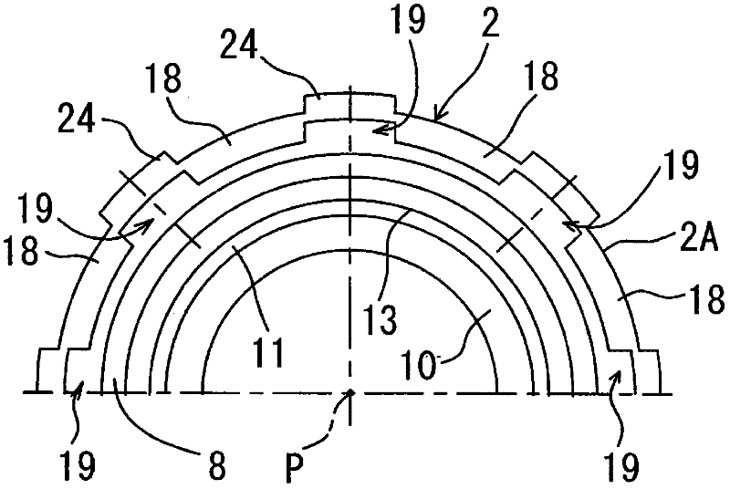
[0084] That is, if Figure 8 As shown, the recess 19 on the union nut 2 of the first embodiment (refer to image 3 etc.) is a shape covered by the protrusion 24 extending in the axis P direction. Thus, if Figure 6 As shown in (c), the part of the convex part 20 entering the concave part 19 can...
no. 3 example
[0089] Such as Figure 9 , Figure 10 , Figure 12 As shown, the resin pipe joint A of the third embodiment is used to connect the pipe 3 made of fluororesin (an example of synthetic resin represented by PFA, PTFE, etc.) Equal pipes are communicated and connected, and the joint main body 1 made of fluororesin (an example of synthetic resin represented by PFA, PTFE, etc.) and fluororesin (an example of synthetic resin represented by PFA, PTFE, etc.) Made of these two components of the union nut 2. also, Figure 9 The tightening completed state (assembled state) after the union nut 2 has been screwed in by a predetermined amount is shown.
[0090] Such as Figure 9 , Figure 10 , Figure 12 As shown, the joint main body 1 is formed as a cylindrical member, and has: an inner cylinder (an example of a fitting cylinder) 4 at one end, which expands the diameter of the end of the pipe 3 and can fit the pipe 3 over the outside; a cover cylinder 6 , which covers the outer perip...
PUM
 Abstract
Description
Claims
Application Information
 - R&D Engineer
- R&D Manager
- IP Professional
- Industry Leading Data Capabilities
- Powerful AI technology
- Patent DNA Extraction
Browse by: Latest US Patents, China's latest patents, Technical Efficacy Thesaurus, Application Domain, Technology Topic.
© 2024 PatSnap. All rights reserved.Legal|Privacy policy|Modern Slavery Act Transparency Statement|Sitemap