Electric control system for crane

An electrical control system and crane technology, applied in the direction of load hanging components, transportation and packaging, etc., can solve the problems of large, sometimes falling down, huge lifting control cabinet structure, large control cabinet volume, etc. Achieve the effect of low board cost, low power consumption and small size

Inactive Publication Date: 2011-11-09
HANGZHOU HOISTING MACHINERY
View PDF7 Cites 1 Cited by
  • Summary
  • Abstract
  • Description
  • Claims
  • Application Information

AI Technical Summary

Problems solved by technology

[0004] (1) Cab control mode, the main feature of this type of control mode is that the master controller in the cab as the main control unit is used as the control mechanism to realize the control logic function, but the power distribution protection cabinet still uses relays and overdrives. The mechanism composed of overlapped flow protectors, so the joint structure is bulky
[0005] (2) Ground operation plus remote control mode. This type of control requires a relatively large number of relays such as relays, because the safety voltage of the ground operation is 36V, but the existence of an intermediate conversion mechanism must be required to control the high voltage of 380V. , which will inevitably require a large number of intermediate relays. On the other hand, if the crane requires more gears, but the number of buttons on the ground operation does not meet the requirements, a delay relay is needed to delay the rest of the gears. As a result, the volume of the control cabinet will become larger and the cost will be higher (for example: a delay head may cost 100-200 yuan depending on the manufacturer and quality)
[0006] 2. In terms of tonnage and working level, generally, cranes above 20T and above A6 safety level must add a separate control cabinet (reverse brake control cabinet) to the main lifting in order to prevent the main hook from sliding during lifting. The function is that at the moment when the high-altitude crane is about to descend, the brake of the crane has been opened, but due to the large tonnage of the heavy object, it will slide down for a while, and once the kinetic energy is large enough, it will exceed the brake of the main hoisting motor. capacity, causing accidents, the adoption of the reverse braking mechanism will add 16-20 intermediate relays and about 10 delay heads, resulting in a huge lifting control cabinet structure and increased costs
[0008] (1) The classical relay control method has been mentioned above. The huge mechanism composed of a large number of intermediate relays and delay heads is not only complicated in wiring, troublesome in installation, but also very expensive.
[0009] (2) The control method of PLC + frequency converter has high control precision. Relatively speaking, the motion control method is more ideal, and the speed adjustment is more continuous. However, if you want to control the entire crane control system at the same time, you need a PLC with many control points. As we all know, foreign countries The cost of PLC is relatively high
[0010] Generally speaking, based on the structure and production method of the current crane control cabinet, the intermediate relays and delay heads in PLCs and control cabinets at home and abroad still have some complicated logic connections. Long, poor wiring, resulting in unstable control of the contactor

Method used


Image

  • Electric control system for crane
  • Electric control system for crane
  • Electric control system for crane

Examples


Embodiment Construction

[0055] Further explain below in conjunction with accompanying drawing:

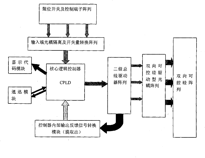
[0056] As shown in 1, the crane electrical control system includes limit switches and control terminal arrays, input optocoupler isolation and switching value conversion arrays, core logic controllers, controller internal output feedback signal conversion modules, output strong and weak current isolation And secondary bus drive module, terminal solid state relay drive array, contactor coil control terminal access terminal; limit switch and control terminal array are connected to the core logic controller through the input end optocoupler isolation and switch value conversion array, and the core logic controller They are respectively connected to the controller's internal output feedback signal conversion module, output strong and weak current isolation and secondary bus drive module, the controller's internal output feedback signal conversion module is connected to the output strong and weak current isolat...


PUM


Abstract

The invention relates to an electric control system for a crane. The system comprises a limit switch and control terminal array, an input end optical coupling isolation and switch quantity conversion array, a core logic controller, a controller internal output feedback signal conversion module, a secondary bus driving module, a bidirectional controlled silicon driven optical coupling array, a bidirectional controlled silicon array, a communication module and a display code module, wherein the limit switch and control terminal array is connected with the core logic controller through the input end optical coupling isolation and switch quantity conversion array; the core logic controller is connected with the controller internal output feedback signal conversion module and the output intensity electric isolation and secondary bus driving module respectively; the controller internal output feedback signal conversion module is connected with the output intensity electric isolation and secondary bus driving module; and the output intensity electric isolation and secondary bus driving module is connected with a contactor coil control terminal connecting end through a terminal solid state relay driving array.

Description

technical field [0001] The invention relates to a crane electrical control system. Background technique [0002] In addition to the bus control mode, the current electrical control system of the crane has the following types from the perspective of tonnage and control mode: [0003] 1. In terms of control methods, there are generally two control methods [0004] (1) Cab control mode, the main feature of this type of control mode is that the master controller in the cab as the main control unit is used as the control mechanism to realize the control logic function, but the power distribution protection cabinet still uses relays and overdrives. The mechanism composed of overlapping flow protectors, so the joint structure is bulky. [0005] (2) Ground operation plus remote control mode. This type of control requires a relatively large number of relays such as relays, because the safety voltage of the ground operation is 36V, but the existence of an intermediate conversion mec...

Claims


Application Information

Patent Timeline
Patent Type & Authority Applications(China)
IPC IPC(8): B66C13/22B66C13/50
Inventor 王磊
Owner HANGZHOU HOISTING MACHINERY
Why Eureka
Try Eureka