Electric pressure fan and electric dust collector having the same

An electric blower, electric technology, applied in vacuum cleaners, components of pumping devices for elastic fluids, machines/engines, etc., can solve the problem of uneven pressure distribution and velocity distribution from the front surface shield to the rear surface shield, energy Loss, increase in energy loss and other issues, to achieve the effect of suppressing uneven distribution of flow velocity, suppressing peeling and backflow, and improving suction work rate

Active Publication Date: 2013-10-09
HITACHI GLOBAL LIFE SOLUTIONS INC
View PDF4 Cites 0 Cited by
  • Summary
  • Abstract
  • Description
  • Claims
  • Application Information

AI Technical Summary

Problems solved by technology

In addition, since there is no detailed adjustment of the angle distribution of the fan blades for the air flow at the inlet, there is also the possibility that near the suction inlet, the inclination of the blades of the impeller is inconsistent with the inflow direction of the air, and the air hits the fan blades. The side of the sheet, the impact loss increases
[0008] In addition, in the electric blower (Patent Document 1), since the blades are greatly inclined with respect to the main plate when viewed from the axial direction, there is a problem of buckling due to buckling in the assembly process using sheet metal. Problems on assembly such as blades or riveting are prone to collapse
[0009] In addition, in the conventional electric blower (Patent Document 1), although the front cover side on the inner peripheral side (inflow side) is inclined to the rotation direction, the outer peripheral side (outflow side) is approximately perpendicular to the rear surface cover, Therefore, on the outer peripheral side (outflow side), the flow of air from the front surface shield to the rear surface shield becomes non-uniform, that is, the pressure distribution and velocity distribution become non-uniform from the front surface shield to the rear surface shield, and there is energy risk of increased losses
[0010] In addition, in a conventional fan (Patent Document 2), when a stationary vane (for example, a diffuser) provided to efficiently decelerate the airflow flowing out from the fan to the downstream of the fan is formed, the In the impeller of the centrifugal fan where the position of the shroud-side coupling portion at the rear edge portion of the blade is shifted by a predetermined amount in the opposite direction of the rotation direction than the position of the hub-side coupling portion, since the matching of the air flow with the stationary blade is not realized, Therefore, separation and reverse flow of the airflow tend to occur between the vanes of the stationary vanes, resulting in energy loss (decreased efficiency)

Method used


Image

  • Electric pressure fan and electric dust collector having the same
  • Electric pressure fan and electric dust collector having the same
  • Electric pressure fan and electric dust collector having the same

Examples


Embodiment 1

[0101] An embodiment of the present invention will be described below using the drawings.

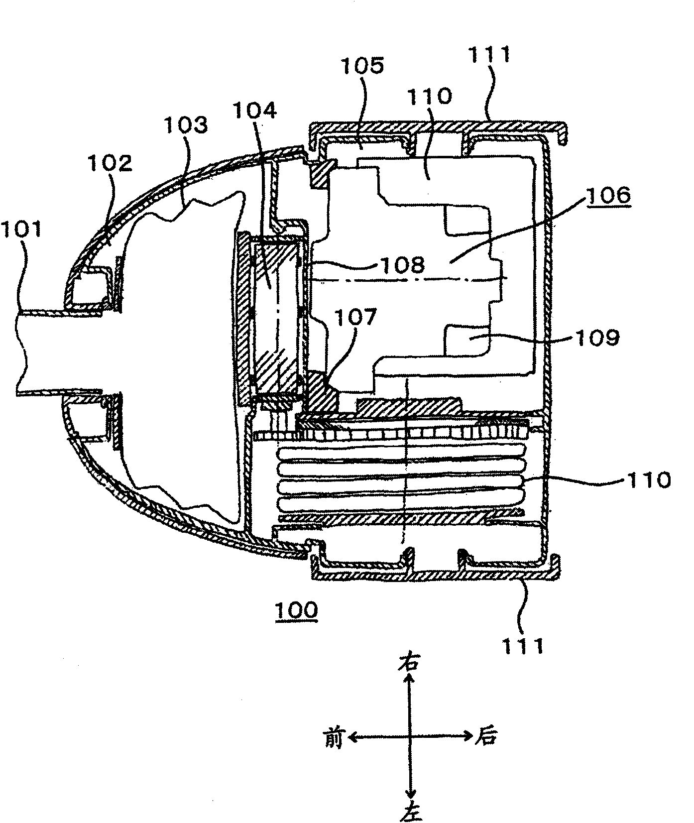
[0102] First, use figure 1 The electric vacuum cleaner main body will be described. Based on from figure 1The structure of the electric vacuum cleaner main body 100 will be described in a transverse sectional view viewed from above of the electric vacuum cleaner main body 100 schematically shown in FIG. The side of the vacuum cleaner body 100 on which the hose joint 101 is attached is defined as the front side of the vacuum cleaner body 100 , and the front end of the vacuum cleaner body 100 has a detachable hose joint 101 . On the front side of the electric vacuum cleaner main body 100, there is a dust collection chamber 102 for holding the paper container 103, and at the rear side of the electric vacuum cleaner main body 100, there is a motor chamber 105 for accommodating the electric blower 106, between the dust collection chamber 102 and the motor Between the chambers 105 , there ...

Embodiment 2

[0131] Since the basic structure is the same as that of Embodiment 1, the same reference numerals are assigned to the same elements and their descriptions are omitted.

[0132] In the above-mentioned manufacturing method based on riveting, when the blade is inclined in the direction of rotation, the blade tends to slide in the direction of rotation during riveting due to the difference in the position of the shroud and the hub in the direction of rotation. question.

[0133] In contrast, as Figure 12 As shown, in Embodiment 2, as described above, with respect to the shroud forming direction of each blade with respect to the hub, the inner edge of the blade is inclined to the direction of rotation, and as it goes between the inner edge and the outer edge of the blade, inclined in the direction opposite to the direction of rotation to form a substantially two-dimensional shape on the hub side, and then, further in the direction opposite to the direction of rotation, become sub...


PUM


Abstract

The invention provides an electric pressure fan and an electric dust collector having the same, with which the situation that air flow from a shield to a wheel hub becomes uneven is prevented; the matching between a static blade disposed at the downstream of a rotating blade and the airflow is realized; the internal loss of the rotating blade and the peeling loss of the internal static blade are reduced. As for the blade, near an inlet, the shield side of the blade inclines towards a rotation direction and then faces the outer edge of the blade. The inclination of the shield side approaches awheel hub side, turning into an approximately two-dimensional shape facing the outer edge of the blade, and the shield side of the blade inclines towards a direction opposite to the rotation direction. When the blade approaches to the outer edge, the inclination towards the direction opposite to the rotation direction is reduced and an approximately two-dimensional shape is formed near the outer edge. Observed from an axial direction, two approximately two-dimensional shapes are provided from the inner edge of the blade to the outer edge of the blade, and inclining shapes with changed rotation direction are provided before and after the approximately two-dimensional shapes.

Description

technical field [0001] The present invention relates to an electric blower and an electric vacuum cleaner equipped with the electric blower. The electric blower has a fan blade in a twisted shape from an inner edge to an outer edge. Background technique [0002] A conventional electric blower is generally composed of a shroud, a main plate arranged at a position facing it, and a plurality of blades arranged therebetween, as shown in the following patent document 1, for example. The hub side is greatly inclined to obtain air volume and vacuum pressure through high-speed rotation. [0003] In particular, Patent Document 1 describes a rotary fan of an electric blower in which the fan blades are clamped by the front surface shroud and the rear surface shroud (hub) and fixed by riveting. Comparing the radius of curvature of the sheet, by making the front surface shield side more inclined than the rear surface shield side, the inner peripheral side, the front surface shield side ...

Claims


Application Information

Patent Timeline
Patent Type & Authority Patents(China)
IPC IPC(8): F04D29/28A47L9/00A47L5/22
Inventor 本多武史坂上诚二冯益祥常乐文夫大平房德川边拓也原田秀行
Owner HITACHI GLOBAL LIFE SOLUTIONS INC
Why Eureka
Try Eureka