Fuse programming circuit and fuse programming method

A fuse and circuit technology, applied in the field of semiconductor devices, can solve the problems of uncertain resistance value, difficult to judge whether the electrical fuse is blown or programmed, etc., and achieves reduced thermal stress, high resistance value, and large inductive margin. Effect

Active Publication Date: 2015-01-21
TAIWAN SEMICON MFG CO LTD
View PDF1 Cites 0 Cited by
  • Summary
  • Abstract
  • Description
  • Claims
  • Application Information

AI Technical Summary

Problems solved by technology

The magnitude of the fuse current of the electrical fuse 102 will exceed the threshold / tolerance value (Threshold) of the electrical fuse 102, so as to cause the electrical fuse 102 to be blown or programmed
However, Figure 1A The fuse-programmed circuit shown, especially after various variations in program, voltage, and temperature (PVT), often causes electrical fuses to produce variable resistance values ​​after blowing, while resistors In the case of large variation and small sensing range, it is not easy to judge whether the electric fuse has actually been blown or programmed

Method used


Image

  • Fuse programming circuit and fuse programming method
  • Fuse programming circuit and fuse programming method
  • Fuse programming circuit and fuse programming method

Examples


Embodiment Construction

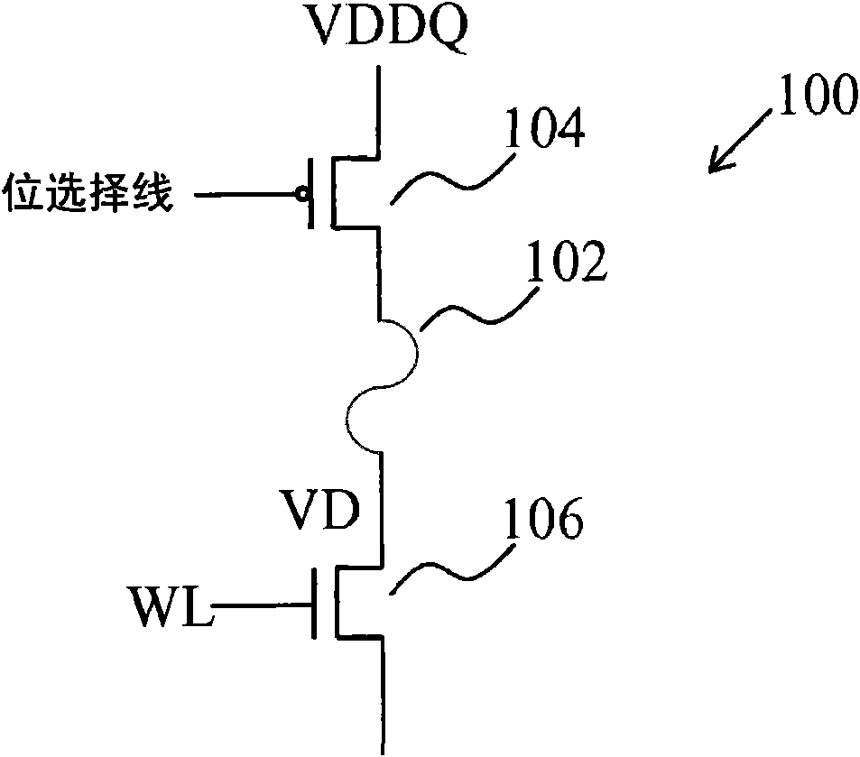
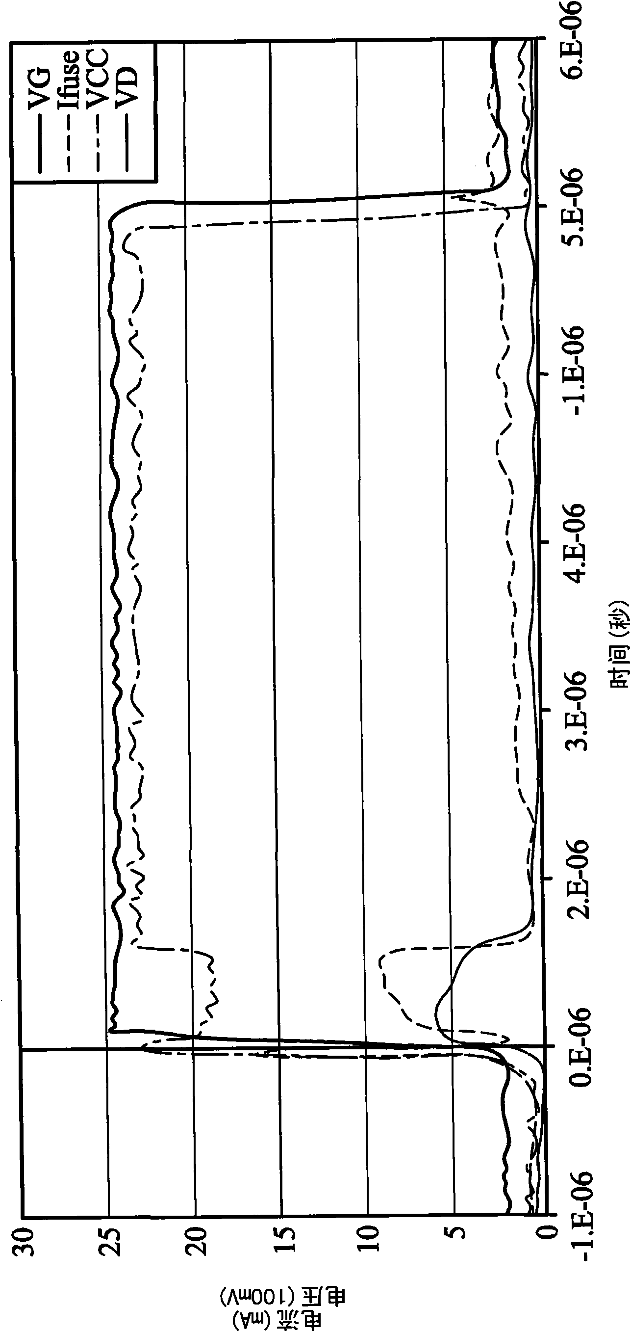
[0042] figure 2 The relationship between voltage and current when the fuse programming circuit receives a programming pulse with a pulse width of approximately 5μs. Such as figure 2 As shown, when approaching t=0 μs, a programming pulse VG will be transmitted to the gate of the NMOS transistor 106 shown in FIG. 1, and the programming pulse VG will turn on the N-type transistor 106, causing a fuse current Ifuse to flow. Via the electrical fuse 102. When the fuse current Ifuse through the electrical fuse 102 increases, the drain voltage VD and the test voltage VDDQ of the NMOS transistor 106 will temporarily decrease.

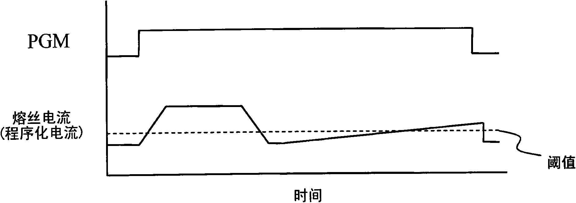
[0043] When approaching t=1 μs, the fuse current Ifuse almost reaches zero amps, which means that the electrical fuse 102 has been melted or has been blown. After t=1 μs, since the fuse current Ifuse starts to flow back to the electrical fuse 102, the fuse current Ifuse will gradually increase in the remaining pulse width of the programmed pulse VG. The fuse cur...


PUM


Abstract

A circuit includes a fuse and a sensing and control circuit. The fuse is coupled between a MOS transistor and a current source node. The sensing and control circuit is configured to receive a programming pulse and output a modified programming signal to the gate of the MOS transistor for programming the fuse. The modified programming signal has a pulse width based on a magnitude of a current through the first fuse.

Description

Technical field [0001] The present invention relates to semiconductor devices, and particularly to the programming of electrical fuses formed in integrated circuits. Background technique [0002] Electrical fuses are often included in integrated circuits and are blown in a specific mode to program certain integrated circuits. Figure 1A It is a well-known fuse programming circuit 100. As shown in the figure, an electrical fuse 102 is connected between an NMOS transistor 106 and a PMOS transistor 104. The PMOS transistor 104 has a gate coupled to the bit selection line, a source coupled to a power supply, and a drain coupled to the electric fuse 102. The NMOS transistor 106 has a gate coupled to a word line WL, a source coupled to the electrical fuse 102, and a drain coupled to the ground. [0003] The electrical fuse 102 is programmed by applying a logic 0 to the gate of the PMOS transistor 104 and a programming pulse with a logic 1 to the gate of the NMOS transistor 106. When a ...

Claims


Application Information

Patent Timeline
Patent Type & Authority Patents(China)
IPC IPC(8): G11C17/16
CPCG11C17/18G11C17/16
Inventor 陈柏宏林松杰许国原黄建程
Owner TAIWAN SEMICON MFG CO LTD
Why Eureka
Try Eureka