Laser melting and etching marking device and method based on transparent material
A transparent material, laser melting technology, applied in the field of micro-machining, can solve the problems of increasing processing procedures, complicated processes, etc., and achieve the effects of high forming quality, low cost, and simple device
- Summary
- Abstract
- Description
- Claims
- Application Information
AI Technical Summary
Problems solved by technology
Method used
Image
Examples
Embodiment 1
[0050] Example 1: Making the "Auspicious Year of the Rabbit" pattern on 3.2mm thick ultra-clear glass
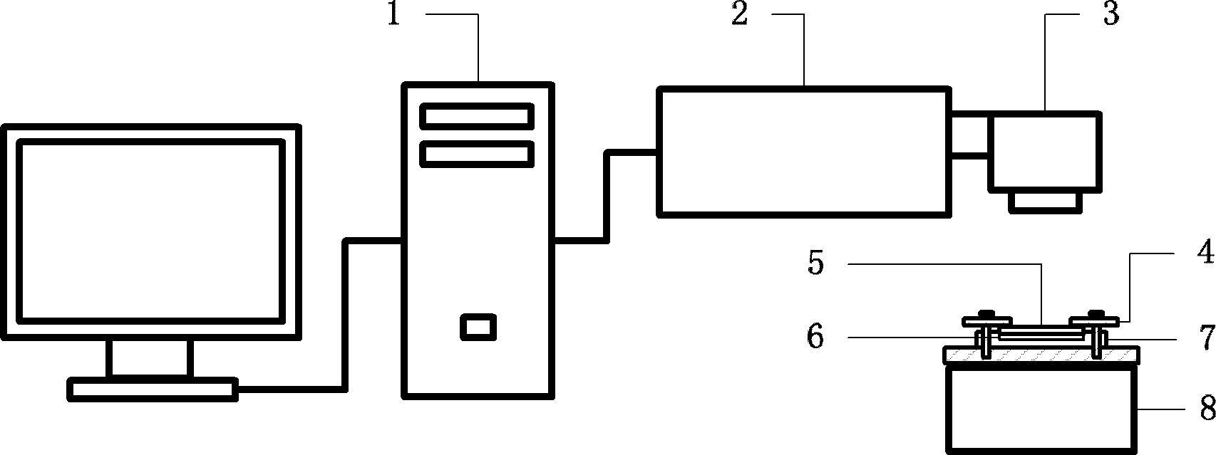
[0051] Will Al 2 o 3 Spread the powder evenly in the plexiglass groove base until the entire groove is filled, and scrape off the excess powder so that the upper surface of the powder is level with the upper surface of the groove base, the depth of the groove is 1mm, and the plane size is 32mm×22mm. Cover the powder with ultra-clear glass with a thickness of 3.2mm and a plane size of 30mm×18mm, compact it evenly, and place it on the fixture to clamp it. Then put it on the workbench, and focus the laser on the plane where the ultra-clear glass contacts the heat-conducting powder. The outline size of the pattern to be marked is 30mm×20mm, and the picture pixel is 300dpi. After importing into the computer, align the marked transparent acrylic board outline with the instruction laser emitted by the laser. Set the processing parameters as laser power 20W, scanning speed 300mm...
Embodiment 2
[0052] Example 2: Making precise scribe lines on 3.2mm thick ultra-clear glass
[0053] Will Al 2 o 3 Spread the powder evenly in the plexiglass groove base until the entire groove is filled, and scrape off the excess powder so that the upper surface of the powder is level with the upper surface of the groove base, the depth of the groove is 1mm, and the plane size is 32mm×22mm. Cover the powder with ultra-clear glass with a thickness of 3.2mm and a plane size of 30mm×15mm, compact it evenly, and place it on the fixture to clamp it. Then put it on the workbench, and focus the laser on the plane where the transparent acrylic is in contact with the heat-conducting powder. Draw a horizontal straight line with a length of 20mm and a line width of 0.15mm in the control software of the computer, set the processing parameters as laser power 20W, scanning speed 300mm / s and frequency 20KHZ. Turn on the laser to scan the laser according to the set processing parameters, and the numbe...
Embodiment 3
[0054] Example 3: Making the "Auspicious Year of the Rabbit" pattern on a 2mm thick transparent acrylic
[0055] Will Al 2 o 3 Spread the powder evenly in the plexiglass groove base until the entire groove is filled, and scrape off the excess powder so that the upper surface of the powder is level with the upper surface of the groove base, the depth of the groove is 1mm, and the plane size is 32mm×22mm. Cover the powder with a transparent acrylic with a thickness of 2mm and a plane size of 30mm×20mm, compact it evenly, and place it on a jig to clamp it. Then put it on the workbench, and focus the laser on the plane where the transparent acrylic is in contact with the heat-conducting powder. The outline size of the bunny pattern to be marked is 30mm×20mm, and the picture pixel is 300dpi. After importing to the computer, the instruction laser emitted by the laser is aligned with the outline of the marked transparent acrylic plate. Set the processing parameters as laser power ...
PUM
| Property | Measurement | Unit |
|---|---|---|
| melting point | aaaaa | aaaaa |
| thermal conductivity | aaaaa | aaaaa |
| surface roughness | aaaaa | aaaaa |
Abstract
Description
Claims
Application Information
 - R&D
- Intellectual Property
- Life Sciences
- Materials
- Tech Scout
- Unparalleled Data Quality
- Higher Quality Content
- 60% Fewer Hallucinations
Browse by: Latest US Patents, China's latest patents, Technical Efficacy Thesaurus, Application Domain, Technology Topic, Popular Technical Reports.
© 2025 PatSnap. All rights reserved.Legal|Privacy policy|Modern Slavery Act Transparency Statement|Sitemap|About US| Contact US: help@patsnap.com


