Operation method of powder sintering device

An operation method and powder technology are applied in the field of operation of powder sintering equipment, which can solve the problems of increasing the scale of powder sintering equipment and so on.

Active Publication Date: 2015-01-14
NGK INSULATORS LTD
View PDF3 Cites 0 Cited by
  • Summary
  • Abstract
  • Description
  • Claims
  • Application Information

AI Technical Summary

Problems solved by technology

In such a case, there is an unsatisfactory problem from the viewpoint of saving space that it is necessary to provide a long and large powder cooling space for cooling the powder in a hypoxic environment, so that the powder The scale of firing equipment becomes larger

Method used


Image

  • Operation method of powder sintering device
  • Operation method of powder sintering device
  • Operation method of powder sintering device

Examples


Embodiment Construction

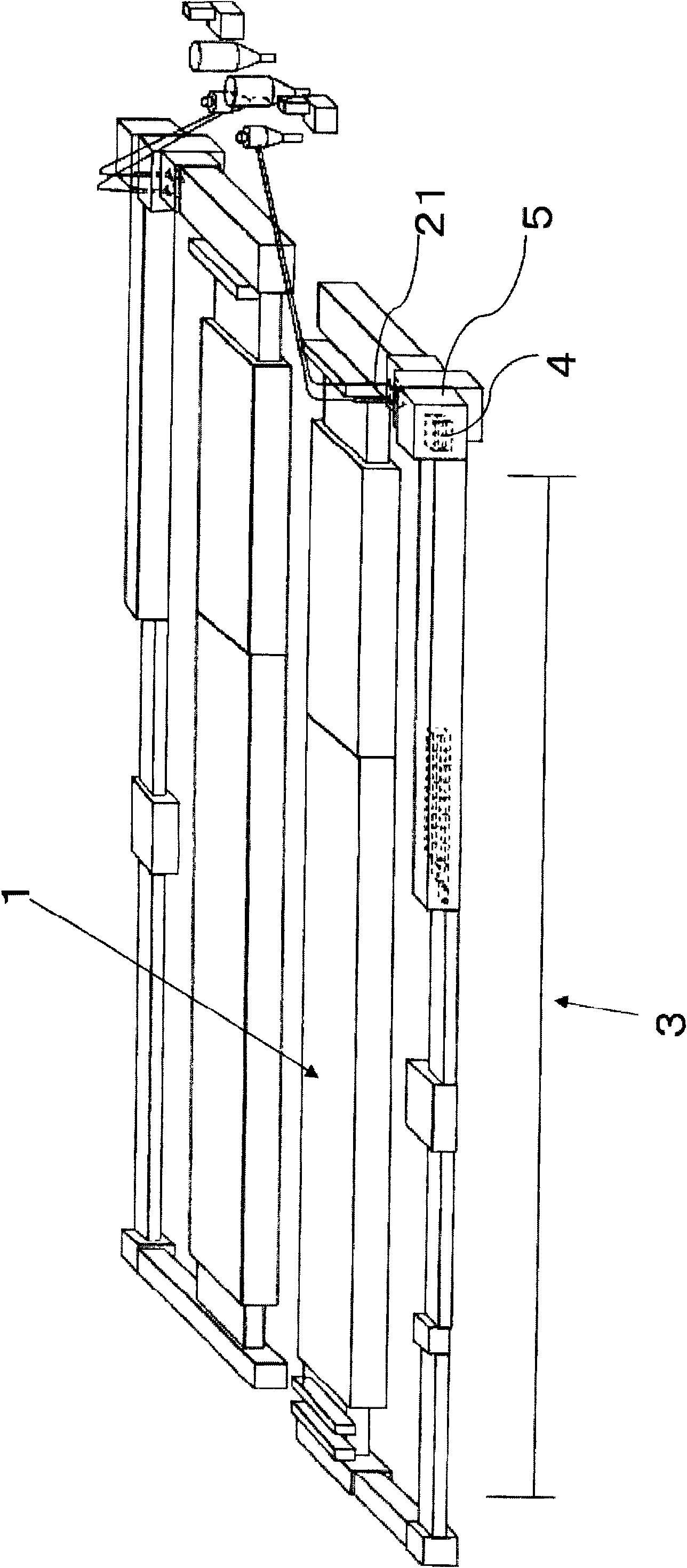
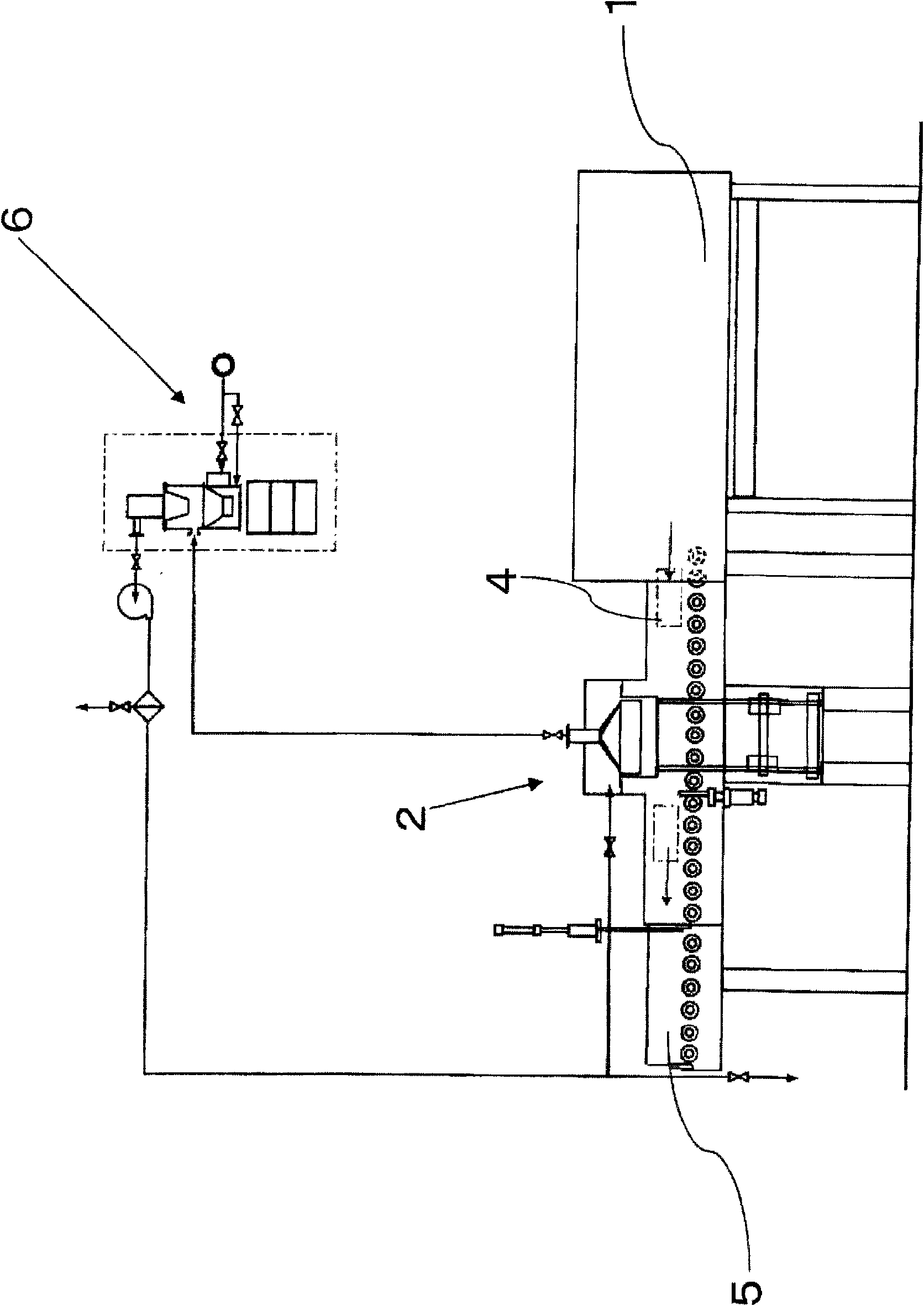
[0033] Next, preferred embodiments of the present invention are shown. figure 1 It is a diagram for explaining the overall structure of powder firing equipment, figure 2 It is a figure for explaining the powder recovery unit used in the powder recovery process, and in each drawing, 1 indicates a continuous firing furnace, 2 indicates a powder recovery unit, 3 indicates an empty sagger conveyance path, and 4 Indicates a sagger.

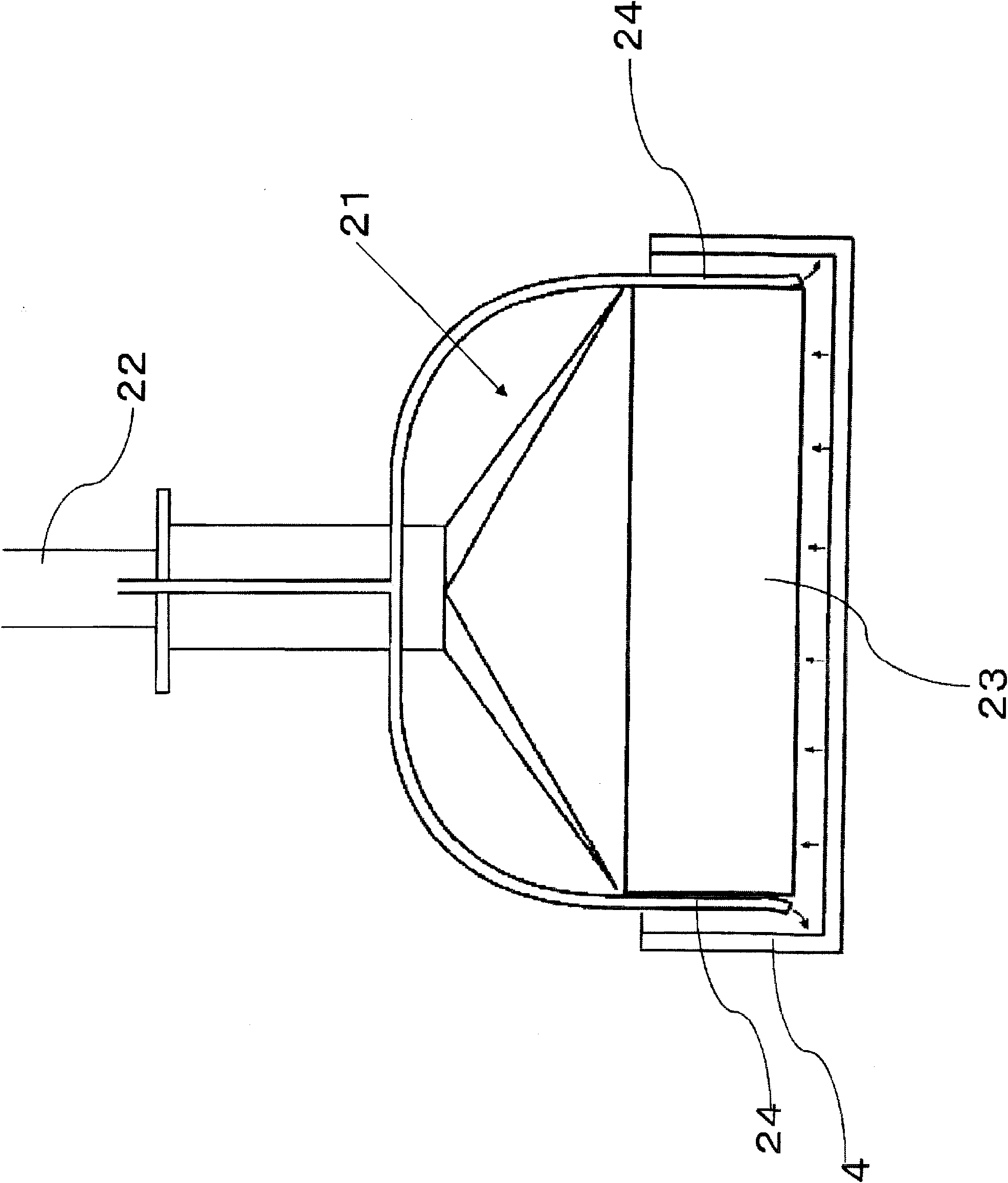
[0034] Such as figure 2 As shown, the powder recovery unit 2 has a powder suction nozzle 21 for sucking the powder in the sagger and a conveyance path 22 for conveying the powder sucked by the powder suction nozzle 21, and, as image 3 and Figure 4 As shown, the powder suction nozzle 21 has a scraper-shaped suction port 23 whose long side is approximately equal to the length of one side of the sagger, and has a gas nozzle 24 on the outer surface of the short side of the suction port 23 .

[0035] Such as figure 1 As shown, the powder sintering...


PUM


Abstract

The invention provides an operation method of a powder sintering device. Powder sintering can be completed under various sintering conditions without a large-scale powder sintering device, when saggars are used for powder sintering. The operation method, a method for moving saggars of the powder sintering device, includes a continuous sintering step where the saggars containing powder are moved from one end to another of a furnace for sintering, a powder recovery step where powder is taken out from the continuous sintering furnace, and an empty saggars moving step where the saggars of which the contained powder is taken out is moved to next process. In the powder recovery step, powder is recovered through a powder nozzle with a scraper shaped sucking mouth which sucks powder in layer manner. The length of a long edge of the scraper shaped sucking mouth equals to the length of one edge of a saggar.

Description

technical field [0001] The present invention relates to a method for operating a powder sinter plant. Background technique [0002] When firing raw material powder for electronic industrial products, the powder is usually placed in a kiln furniture called a sagger and fired (for example, Patent Document 1). Continuous firing is carried out in industrial production. Saggers are put into the furnace sequentially from one end of the continuous furnace with a predetermined firing temperature curve, fired while moving in the furnace, and then taken out from the other end. [0003] The powder in the sagger taken out from the other end of the continuous firing furnace is recovered in the powder recovery step which is the next step. The powder recovery temperature varies depending on the powder. For example, for powders that need to be fired in a low-oxygen environment, some limit the air exposure temperature after firing to below 50°C. Positive-electrode material (positive-electr...

Claims


Application Information

Patent Timeline
Patent Type & Authority Patents(China)
IPC IPC(8): C04B35/64
CPCC04B35/626C04B35/64C04B2235/70
Inventor 野入一二夫青木道郎
Owner NGK INSULATORS LTD
Why Eureka
Try Eureka