Four-point contact ball bearing
A four-point contact, ball bearing technology, applied in the direction of ball bearings, shafts and bearings, bearing components, etc., can solve the problems of affecting the normal use of bearings, reducing bearing accuracy, increasing the difficulty of assembly, etc., to improve friction and wear and development. Heat, reduce wear and heat, improve the effect of assembly accuracy
- Summary
- Abstract
- Description
- Claims
- Application Information
AI Technical Summary
Problems solved by technology
Method used
Image

Examples
Embodiment Construction
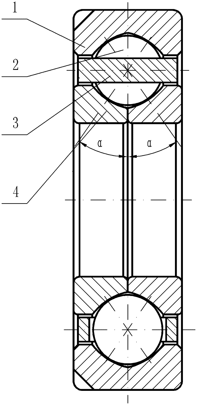
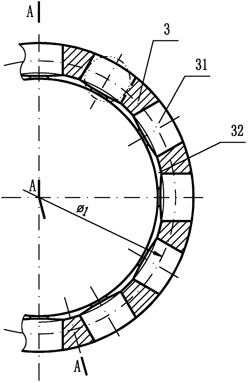
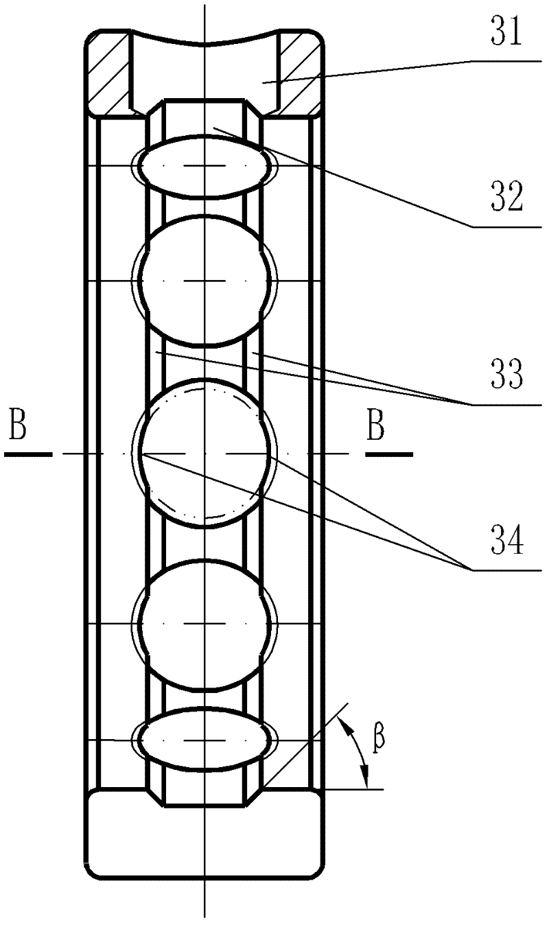
[0019] See Figure 1-7 As shown, the four-point contact ball bearing of the present invention includes an outer ring 1, two separate inner rings 4, rolling elements 2 and a cage 3, and pocket holes 31 are evenly distributed on the cage 3 along the circumferential direction, as shown in figure 1 As shown, 12 pocket holes 31 can be used, and each rolling element 2 is installed in each pocket hole 31 and arranged between the outer ring 1 and the two inner rings 4, so that the inner ring 4, the outer ring 1 and the rolling elements 2 The cages 3 are combined together to form a bearing. The contact angle d of the four-point contact ball bearing can be 30°, or the contact angle is 35°, or the contact angle is 40° or the contact angle is 45°. Each pocket on the cage 3 is 31 The inner side of the lock is provided with a lock, and the installation center size of the rolling body 2 is φ1. The aperture size of the lock is smaller than the diameter of the rolling body 2. See Figure 2-7...
PUM
 Abstract
Description
Claims
Application Information
 - R&D
- Intellectual Property
- Life Sciences
- Materials
- Tech Scout
- Unparalleled Data Quality
- Higher Quality Content
- 60% Fewer Hallucinations
Browse by: Latest US Patents, China's latest patents, Technical Efficacy Thesaurus, Application Domain, Technology Topic, Popular Technical Reports.
© 2025 PatSnap. All rights reserved.Legal|Privacy policy|Modern Slavery Act Transparency Statement|Sitemap|About US| Contact US: help@patsnap.com