Fan-out signal line structure and display panel

A display panel and signal line technology, applied in nonlinear optics, optics, instruments, etc., can solve problems such as inconsistent resistance values ​​of signal lines, inconsistent lengths of signal lines, and affecting signal transmission quality, so as to ensure signal transmission quality and uniform resistance Value, the effect of improving the resistance difference problem

Inactive Publication Date: 2011-11-16
HANNSTAR DISPLAY CORPORATION
View PDF3 Cites 23 Cited by
  • Summary
  • Abstract
  • Description
  • Claims
  • Application Information

AI Technical Summary

Problems solved by technology

[0004] However, since the signal lines in the fan-out area are distributed in a fan shape, the lengths of all the signal lines in the fan-out area are inconsistent, and there is a problem that the resistance values ​​of the signal lines are inconsistent.
For example, the length of the signal line in the middle of the fan-out area is shorter than the length of the signal line at the outside of the fan-out area, so there is a considerable difference in resistance between the two, which easily affects the transmission quality of the signal, and then causes such as display Problems such as inconsistent brightness and darkness of the screen

Method used


Image

  • Fan-out signal line structure and display panel
  • Fan-out signal line structure and display panel
  • Fan-out signal line structure and display panel

Examples


Embodiment Construction

[0031] The following descriptions of the various embodiments refer to the accompanying drawings to illustrate specific embodiments in which the present invention can be practiced. The directional terms mentioned in the present invention, such as "up", "down", "front", "back", "left", "right", "inside", "outside", "side", etc., are for reference only The orientation of the attached schema. Therefore, the directional terms used are used to illustrate and understand the present invention, but not to limit the present invention.

[0032] In the following embodiments, the same parts are denoted by the same symbols in different drawings.

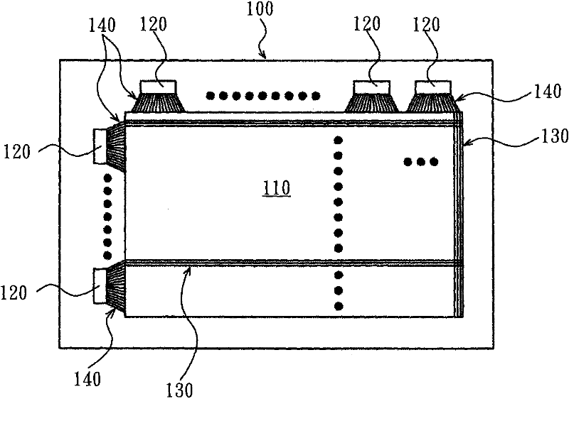
[0033] Please refer to figure 1 , which shows a schematic diagram of the display panel according to the first embodiment of the present invention. The fan-out signal line structure of this embodiment can be applied, for example, to a display panel 100 to extend or spread the electrical path, and the display panel 100 can be applied to various d...


PUM


Abstract

The invention provides a fan-out signal line structure and a display panel. The fan-out signal line structure comprises a plurality of fan-out signal lines and resistance compensating units, wherein the fan-out signal lines are in fan-shaped configuration; and the resistance compensating units are formed on the fan-out signal lines and used for compensating a resistance difference between the fan-out signal lines. The fan-out signal line structure can be applied to the display panel to ensure the quality of signal transmission.

Description

technical field [0001] The present invention relates to a fan-out signal line structure and a display panel, in particular to a fan-out signal line structure and a display panel which can improve the problem of resistance difference between signal lines. Background technique [0002] In the electronic assembly process, such as high-pin-count integrated circuits, or in the flip-chip ball grid array (Ball Grid Array) process of small-area low-pin-count integrated circuits, it is necessary to place the input / output pads on the chip , through the redistribution process (Redistribution Process) to rearrange into an array form (Array). Since the general printed circuit board (Print Circuit Board, PCB) cannot match the integrated circuit with high-density output / input pins in the process layout, it is necessary to bond the flip-chip chip to the high-density substrate first, and then connect the chip through the high-density substrate. The output / input pin conversion fan-out (Fan-o...

Claims


Application Information

Patent Timeline
Patent Type & Authority Applications(China)
IPC IPC(8): G02F1/13H01L23/522
Inventor 陈荣峰李昆政曾汉麟
Owner HANNSTAR DISPLAY CORPORATION
Why Eureka
Try Eureka