Welding method of tandem type solar silicon wafer group and special shelf thereof

A technology of solar silicon wafers and welding methods, which is applied in sustainable manufacturing/processing, electrical components, climate sustainability, etc. It can solve the problems of inconvenient taking of silicon wafer groups, inconsistent distances, and difficult to support and hold, and achieve high operating speed Convenient and quick, reduce fragmentation rate, easy to take effect

Inactive Publication Date: 2011-11-16
SOPRAY ENERGY
View PDF4 Cites 1 Cited by
  • Summary
  • Abstract
  • Description
  • Claims
  • Application Information

AI Technical Summary

Problems solved by technology

When realizing the series connection of silicon wafer groups, it is necessary to constantly turn the silicon wafers, and the silicon wafers are fragile, which may easily cause damage to the silicon wafers during the flipping process, and the distance between two adjacent silicon wafers is not easy to hold, so that different The distance between two adjacent silicon wafers in the silicon wafer group is inconsistent, which will affect the appearance of solar products
For the welded silicon chip group, because the interconnection strips are relatively soft, and the silicon chip group has a certain length, this makes it inconvenient to take the silicon chip group, and it is easy to cause the silicon chip to break during the taking process.

Method used


Image

  • Welding method of tandem type solar silicon wafer group and special shelf thereof
  • Welding method of tandem type solar silicon wafer group and special shelf thereof
  • Welding method of tandem type solar silicon wafer group and special shelf thereof

Examples


Embodiment Construction

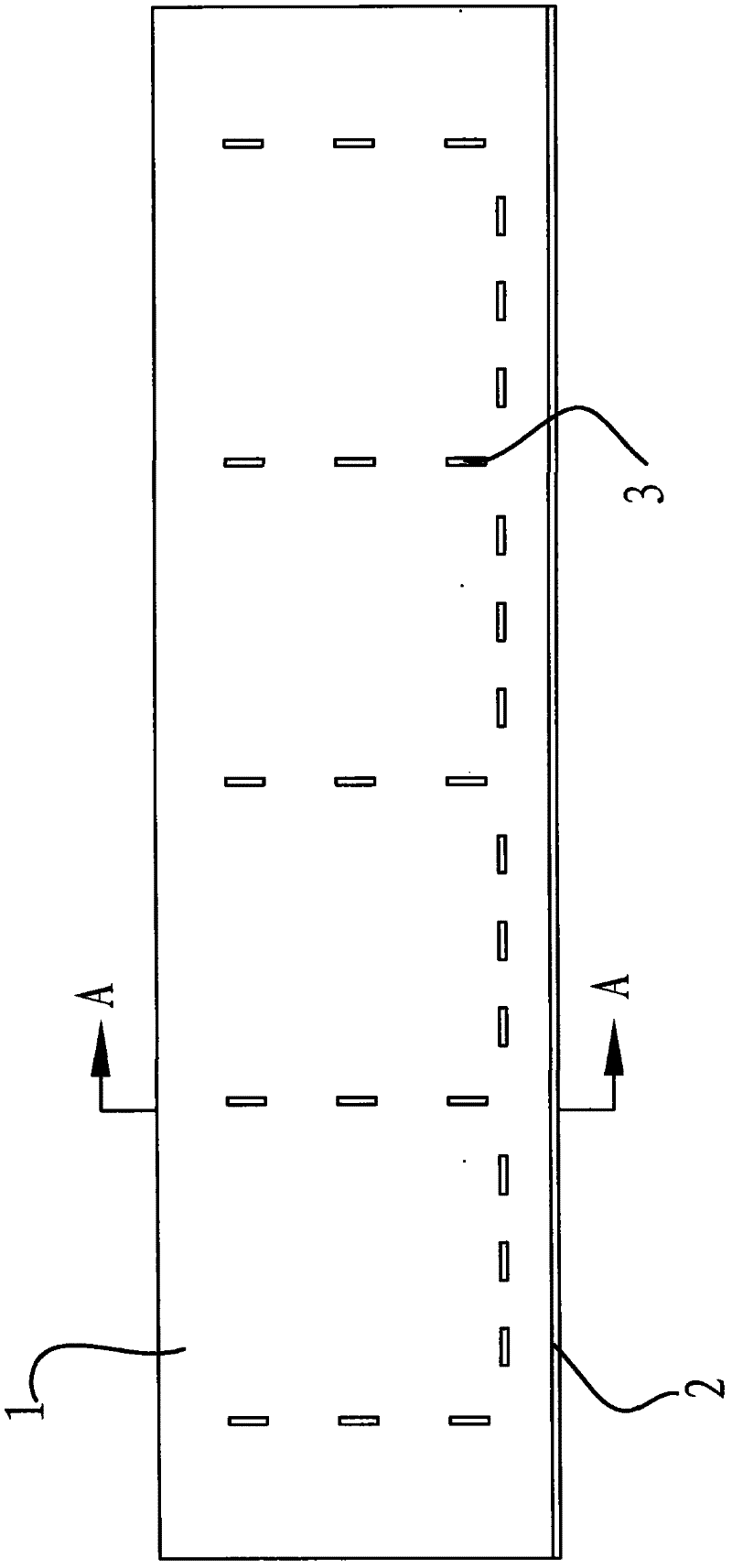
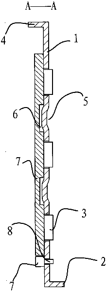
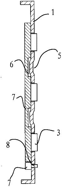
[0020] The tandem solar silicon chip group welding shelf includes a platform and a plate-shaped shelf 1, and the shelf 1 is used to naturally rest on the platform. A heating device is arranged on the back side of the platen. When the shelf 1 is placed on the platen, the shelf is located above the heating device. When the silicon wafer group is welded, the heating device is in an energized state.

[0021] The shelf 1 is provided with several sets of spacers protruding to the outside of the front surface of the shelf 1, and there are intervals between two adjacent sets of spacers in the length direction of the shelf 1, and these intervals are equal. These spaces are slightly larger than the dimensions of the silicon wafers so that the silicon wafers can fit into these spaces.

[0022] There are three spacers 3 in each group of spacers, the three spacers 3 are arranged separately along the width direction of the shelf 1, and the gaps between two adjacent spacers 3 are equal.

[...


PUM


Abstract

The invention relates to a welding method of a tandem type solar silicon wafer group and a special shelf thereof. The shelf comprises a platy shelf; the shelf is provided with a plurality of raised spacer sets; and the spacer sets are arranged at intervals along the length direction of the shelf. The method for welding the solar silicon wafer group comprises the following steps: firstly overlaying silicon wafers with interconnected strips at the back side into a silicon wafer column, wherein the extending ends of all the interconnected strips are positioned at the same side of the silicon wafer column, the silicon wafer column is arranged above the shelf and moves from one end of the shelf to the other end, the moving direction is opposite to the extending direction of the interconnected strips, and in the moving process of the silicon wafer column, the silicon wafers at the most bottom layer are continuously and sequentially placed in different intervals on the shelf; then regulatingthe positions of the silicon wafers in the intervals so that the interconnected strips are overlapped with main grid lines on the adjacent silicon wafers; and finally welding the overlapped interconnected strips and the main grid lines together by utilizing a ferrochrome. The welding method is convenient and rapid, the operation efficiency is high, and the silicon wafers are not easy to crack in the welding process.

Description

technical field [0001] The invention relates to a welding method, in particular to a method for welding a serial solar silicon wafer group and a special shelf thereof. Background technique [0002] As a clean energy source, solar energy is being widely used day by day. Solar energy products are generally composed of multiple single-chip silicon chips connected in a certain way. These silicon chips are generally connected in series into silicon chip groups, and then multiple groups of silicon chip groups are connected together in parallel. There are two parallel main grid lines on the front of a single finished solar silicon chip, and two parallel back electrodes on the back. When the silicon chips are connected in series, they are connected together by copper-based tin interconnection strips. One end of the interconnection bar is welded together with the back electrode of the silicon chip, and the other end is welded together with the main grid line. Under the existing tec...

Claims


Application Information

Patent Timeline
Patent Type & Authority Applications(China)
IPC IPC(8): H01L31/18
CPCY02P70/50
Inventor 焦保贞
Owner SOPRAY ENERGY
Why Eureka
Try Eureka