
Novel CT (Captive Test) machine data acquiring and imaging system

A data acquisition and imaging system technology, applied in computerized tomography scanners, echo tomography, etc., can solve the problems of high current in X-ray tubes, great harm to human body, high waste rate, etc., and achieve simple physical structure and low radiation dose , the effect of high work stability

Inactive Publication Date: 2011-11-23
郭圣华 +1
View PDF3 Cites 2 Cited by
  • Summary
  • Abstract
  • Description
  • Claims
  • Application Information

AI Technical Summary

Problems solved by technology

It has the following defects: Since the scale of each row of detection units is in the range of 0.65mm to 1mm, the minimum distance between faults is 0.65mm, that is, the smallest pixel that can be resolved on the image corresponds to the object to be inspected is also 0.65mm, less than The structure of 0.65mm cannot be seen clearly; it is very difficult to manufacture hundreds of units of a line array so that the sensitivity parameters, linear parameters, reading speed parameters and many other parameters are completely consistent, so the scrap rate in the manufacturing process This is one of the important reasons for the high price of the CT machine; it requires a large power of the X-ray tube, generally working at 500mA-800mA, which not only costs high, but also has large radiation, which is harmful to human body. The body is harmful, and the power consumption is also high; the shorter the scanning time, the better the accuracy and consistency of the tomographic data, which requires that the scanning rotating part needs to work in a high-speed rotating state, and high-speed rotating requires the physical performance of the machine equipment Very high, high voltage supply, signal transmission needs to pass through complex slip rings, and the equipment manufacturing cost is correspondingly much higher
[0004] In short, the distance between adjacent slices of the existing CT machine is large, and the slice distance and the minimum resolution are at least 0.65mm; one scan obtains few slice images, each detection requires multiple scans, and the scan speed is slow; the current of the X-ray tube is large, High cost, large radiation, and high radiation dose to patients; the requirement of high-speed rotation increases the complexity and manufacturing cost of the machine

Method used


Image

  • Novel CT (Captive Test) machine data acquiring and imaging system
  • Novel CT (Captive Test) machine data acquiring and imaging system
  • Novel CT (Captive Test) machine data acquiring and imaging system

Examples


Embodiment 1

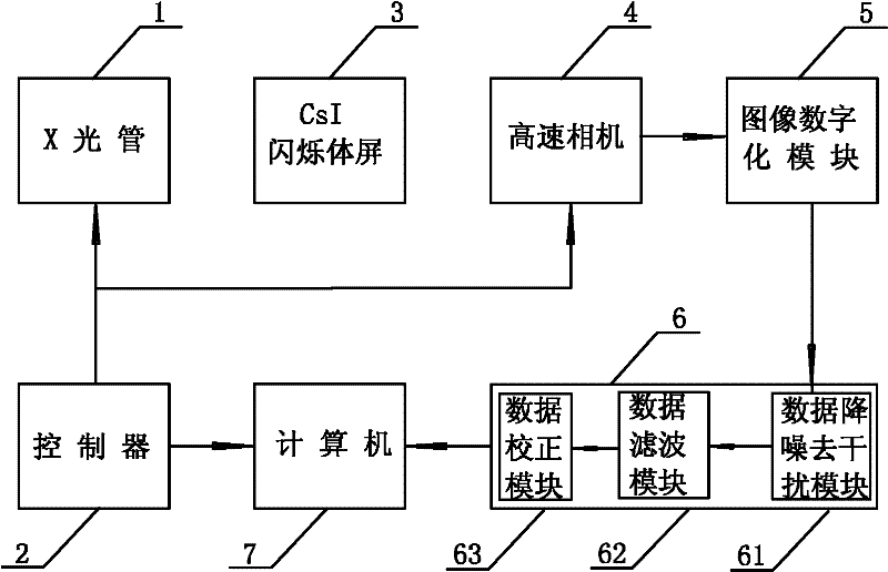
[0016] like figure 1 As shown, a novel CT machine data acquisition imaging system includes an X-ray tube 1, a controller 2, a CsI scintillator screen 3, a high-speed camera 4, an image digitization module 5, a data processing module 6, and a computer 7; the controller 2 Electrically connect the X-ray tube 1, the high-speed camera 4 and the computer 7 respectively, the high-speed camera 4, the image digitization module 5, the data processing module 6, and the computer 7 are electrically connected in sequence; use the CsI scintillator screen 3 as the imaging screen When, the CsI scintillator screen 3 is not electrically connected with the controller 2, it is between the detected object and the high-speed camera 4;

[0017] The data processing module 6 includes a data noise reduction and interference removal module 61 , a data filtering module 62 , and a data correction module 63 connected in sequence.

Embodiment 2

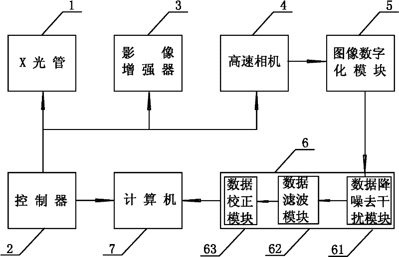
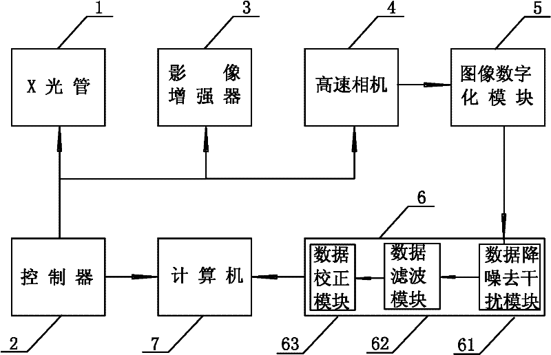
[0019] like figure 2 As shown, a novel CT machine data acquisition imaging system includes an X-ray tube 1, a controller 2, an image intensifier 3, a high-speed camera 4, an image digitization module 5, a data processing module 6, and a computer 7; the controller 2 The X-ray tube 1, the image intensifier 3, the high-speed camera 4 and the computer 7 are respectively electrically connected, and the high-speed camera 4, the image digitization module 5, the data processing module 6, and the computer 7 are electrically connected sequentially;

[0020] The data processing module 6 includes a data noise reduction and interference removal module 61 , a data filtering module 62 , and a data correction module 63 connected in sequence.

[0021] The working principle and working process of the present invention are as follows:

[0022] like figure 1 , 2 As shown, the detected object is placed between the X-ray tube 1 and the CsI scintillator screen 3 (or image intensifier 3); the X-r...


PUM


Abstract

The invention discloses a novel CT (Captive Test) machine data acquiring and imaging system comprising an X-ray tube, a controller, an imaging screen, a high-speed camera, an image digitizing module, a data processing module and a computer, wherein the controller is respectively and electrically connected with the X-ray tube, the imaging screen, the high-speed camera and the computer, and the high-speed camera, the image digitizing module, the data processing module and the computer are electrically connected in sequence. The novel CT machine data acquiring and imaging system has the beneficial effects that imaging can be finished by one-time scanning, thus the radiation dose on the tested objected is low; the resolving power is higher, and the layer space is smaller, so that clinicopathologic features which are difficult to detect by the common CT machine are easy to detect by the novel CT machine data acquiring and imaging system; the X-ray filter of the tested object can be digitalized to obtain a 360-degree omnibearing DR (Dead Reckoning) filter to realize the purpose of one machine with multiple purposes; the high-speed camera and the small-power X-ray tube are low in cost; the system does not need to rotate at a high speed; and the novel CT machine data acquiring and imaging system has the advantages of simple physical structure, low production cost and high working stability.

Description

technical field [0001] The invention belongs to the technical field of medical equipment, and in particular relates to a novel CT machine data acquisition and imaging system. Background technique [0002] In the prior art, the working principle of a computerized tomography imaging machine, that is, what we usually call a CT machine, is to use a beam of X-rays to irradiate the detected object without destroying the structure of the object. The projection data of the X-ray intensity of the detection object is used to reconstruct the two-dimensional image of the specific section of the object through computer processing by using certain mathematical methods. In medicine, using CT machines, doctors can clearly observe the body tissue conditions that are difficult to show on ordinary X-ray films, such as cerebral hemorrhage and various small tumors, etc., which has significantly improved the level of clinical diagnosis. [0003] At present, the collection process of X-ray projec...

Claims


Application Information

Patent Timeline
IPC IPC(8): A61B6/03
Inventor 郭圣华孙峰
Owner 郭圣华
Learn More