

Expansion tank liquid level pressure stabilization device in closed water-cooling circulating system
A circulation system and pressure stabilization technology, applied in the cooling of the engine, engine components, machines/engines, etc., can solve problems affecting normal production and operation, achieve small and unstable liquid level pressure changes, and simplify the expansion tank Voltage stabilization system, reducing the effect of equipment
- Summary
- Abstract
- Description
- Claims
- Application Information
AI Technical Summary
Problems solved by technology
Method used
Image

Examples
Embodiment approach 1
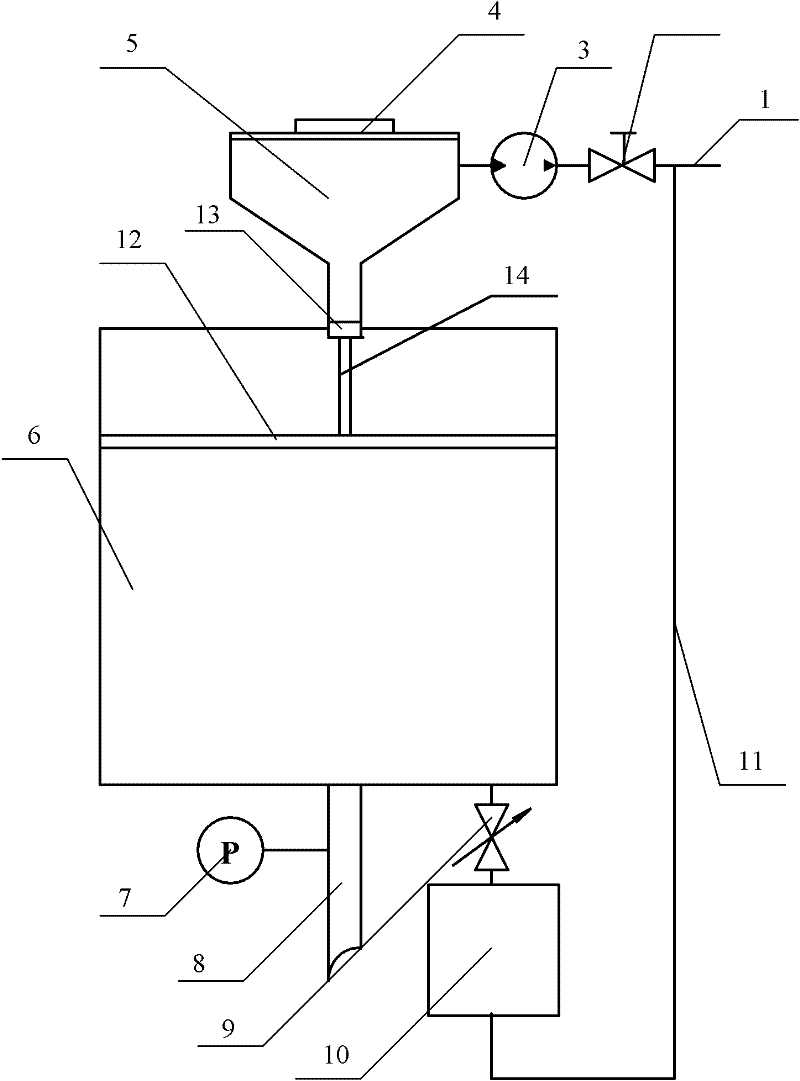
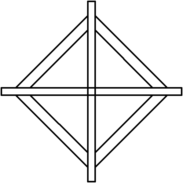
[0017] Generally, the expansion tank is set at the highest point of the system, so the expansion tank in this embodiment is not equipped with nitrogen, so that the storage capacity of pure water in the expansion tank becomes larger, and the system can be replenished by the gravity of water. The liquid level pressure stabilizing device of the expansion tank in the closed circulation water cooling system of this embodiment is as follows: figure 1 shown. A funnel-shaped container 5 is installed on the top of the expansion tank 6, and the top of the funnel-shaped container 5 is a sealing cover 4. Funnel-shaped container 5 and expansion tank 6 are welded together. The inside of the expansion tank 6 is equipped with a float, and the structure of the bottom 12 of the float is as follows: figure 2 As shown, such a structure is to make the float float well on the water. The inner wall of the expansion tank 6 has a slideway suitable for a cross structure, and the length of the slide...
Embodiment approach 2
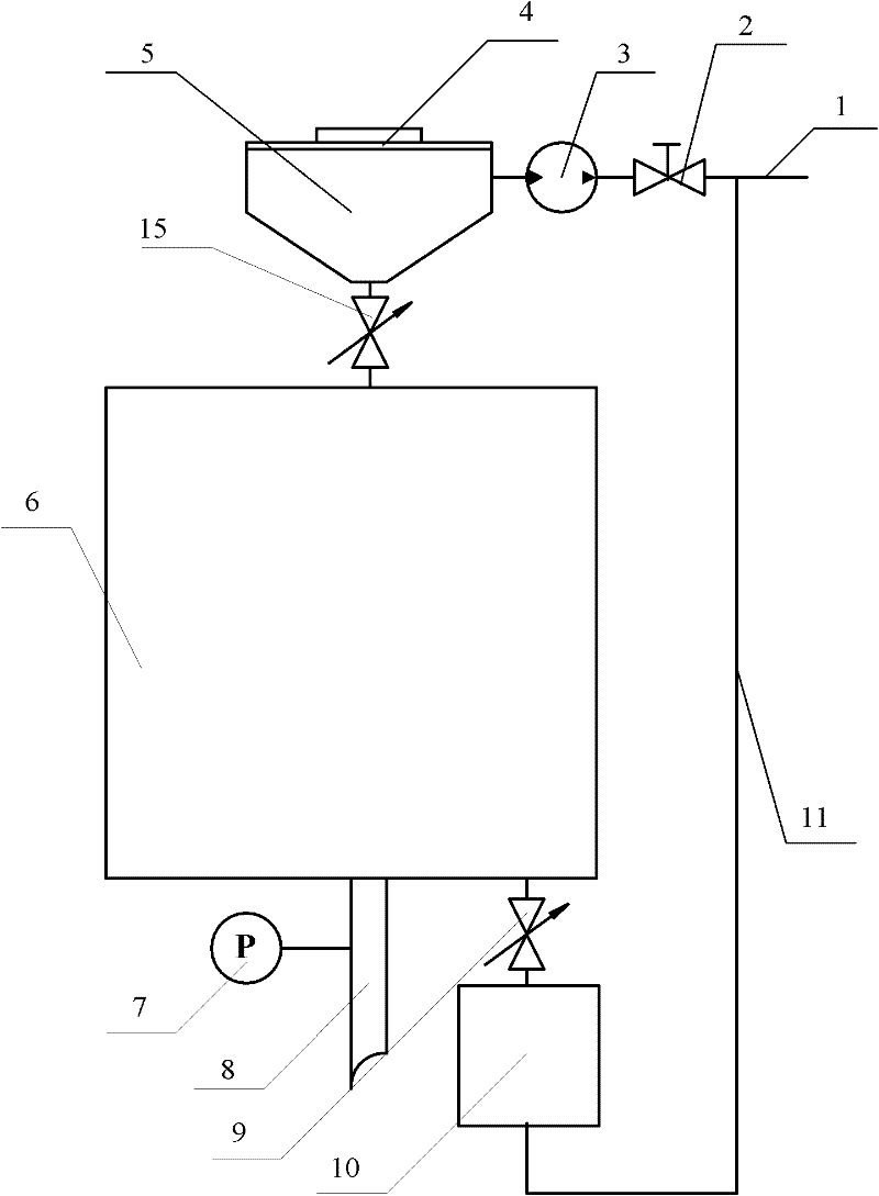
[0021] see image 3 , On the basis of Embodiment 1, no float is installed inside the expansion tank 6, and no slideway is opened on the inner wall of the expansion tank 6, that is, the float structure is not used. An electric valve 15 is installed at the connecting pipe between the funnel-shaped container 5 and the expansion tank 6 . In the initial water injection of the closed circulation water cooling system, the electric valve 15 is opened, and when the water quantity in the expansion tank 6 reaches the maximum value of the liquid level pressure allowed (set) by the system, the electric valve 15 is closed. During the operation of the closed circulation water cooling system, when the liquid level pressure of the expansion tank 6 is lower than the minimum value of the liquid level pressure allowed by the system, the electric valve 15 is opened, and when the water volume in the expansion tank 6 reaches the allowable (set) value of the system When the liquid level pressure rea...
PUM
 Abstract
Description
Claims
Application Information