
Detonation performance test method for high-energy imploding explosive

A technology of detonation performance and test method, applied in the field of high-energy internal explosive detonation performance test, can solve the problems of high test cost, inability to accurately quantitatively compare, inability to flexibly select test environment, etc. Effect

Inactive Publication Date: 2011-11-23
XIAN MODERN CHEM RES INST
View PDF3 Cites 76 Cited by
  • Summary
  • Abstract
  • Description
  • Claims
  • Application Information

AI Technical Summary

Problems solved by technology

[0004] (1) The test needs to build a semi-underground device, the site requirements are strict, and the test cost is high;
[0005] (2) Only the air medium test can be used, and the test environment cannot be flexibly selected;
[0006] (3) Using high-speed photography to compare test results is a semi-quantitative method and cannot be compared accurately and quantitatively

Method used


Image

  • Detonation performance test method for high-energy imploding explosive
  • Detonation performance test method for high-energy imploding explosive
  • Detonation performance test method for high-energy imploding explosive

Examples


Embodiment 1

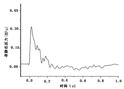
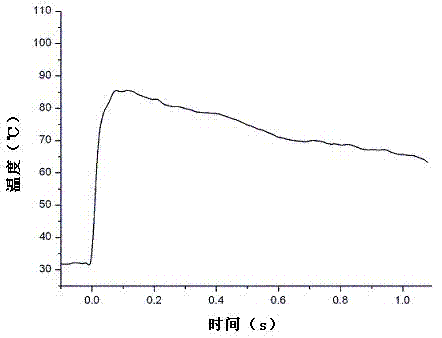
[0054] Present embodiment is that the TNT explosive of 20g carries out quasi-static pressure, transient temperature, detonation velocity, gas composition test in air medium, and its test method comprises the following steps:

[0055] 1) Press 20g of explosive samples from the same batch of tests into a cylindrical explosive column 6 of the same specification, and leave a detonator hole with a diameter of 7mm and a depth of 10-15mm on the explosive column 6. The compressed explosive grain column 6 is stored in the explosive temporary storage area;

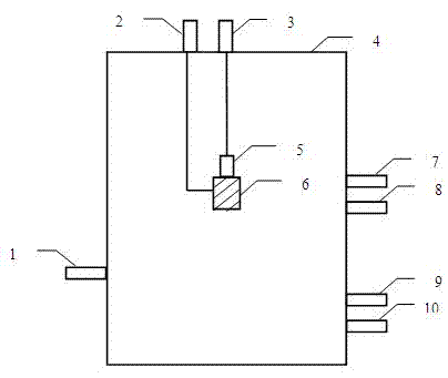
[0056] 2) Arrange the detonator, detonation velocity test equipment, pressure sensor, temperature sensor, and gas collection and test system at the corresponding interface of the explosion vessel, and connect the temperature sensor and pressure sensor to the corresponding paperless recorder and temperature transmitter respectively. , data acquisition instrument, and oscilloscope are connected for data recording. Debug the instrumen...

Embodiment 2

[0080] Present embodiment is to test respectively the quasi-static pressure, transient temperature, detonation velocity, gas composition test of the PBXIH-18 explosive of 10g, 15g, 31g, 40g, and experimental procedure is identical with embodiment 1, and its experimental data are as shown in table 2:

[0081] Table 2 PBXIH-18 explosion gas expansion test data

[0082]

[0083] The calculation results obtained from the test data of this embodiment are shown in Table 3, the test data is calculated according to formula (1), and compared with the reference value E TNT The test results were divided to obtain the ratio, which is used to characterize the strength of work ability. The results are shown in Table 3.

[0084] table 3 E PBX-IH and E TNT The result comparison

[0085]

[0086] It can be seen from Table 3 that the working ability of PBX-IH explosive is far greater than that of 20gTNT, and with the increase of the amount of PBX-IH, E PBX-IH also gradually incr...


PUM


Abstract

The invention discloses a detonation performance test method for high-energy imploding explosive. The method is characterized in that: a explosive grain with a detonator is placed in a sealed explosion vessel; quasi-static pressure of the explosive, transient temperature of the explosive, detonation velocity of the explosive and gas components of the explosive are detected; a temperature sensor is arranged on the sealed explosion vessel, and is provided for monitoring the temperature changing in the sealed explosion vessel during the test process, a pressure sensor is arranged on the sealed explosion vessel, and is provided for monitoring the pressure changing in the sealed explosion vessel during the test process; the sealed explosion vessel is further connected with a gas collection andtest system, a firing device, a detonation velocity test device, a mechanical vacuum pump and a gas cylinder. The method is applicable for the performance tests of various imploding explosives, and can be provided for performing laboratory quantitative evaluation to the gas expansion working.

Description

technical field [0001] The invention belongs to the technical field of propellants and explosives, and in particular relates to a method for testing the detonation performance of high-energy internal explosives, which can evaluate the ability of high-energy internal explosives to expand and perform work in closed air or other ambient atmospheres. Background technique [0002] With the rapid development of military technology, the scope of modern combat and defense has been greatly expanded, from land to solid underground fortifications and underwater targets. Ammunition technology has evolved along with it. For example, ground-penetrating bombs to deal with underground targets; underwater explosive bombs developed to efficiently damage submarines and surface ships. These munitions used in non-open air environments are fast-growing implosion munitions. Detonation of an explosive charge inside a target structure produces damage many times more intense than detonation on the ...

Claims


Application Information

Patent Timeline
Patent Type & Authority Applications(China)
IPC IPC(8): G01N25/54
Inventor 刘红妮胡岚宋浦张皋严蕊王婧娜陈曼张婷
Owner XIAN MODERN CHEM RES INST
Learn More