
Optical fiber coupled connector

An optical fiber coupling and connector technology, applied in the field of optical fiber coupling connectors, can solve the problems of increasing the value of insertion loss, affecting the efficiency of optical signal data, etc., to achieve the effect of improving efficiency

Inactive Publication Date: 2011-11-23
HONG FU JIN PRECISION IND (SHENZHEN) CO LTD +1
View PDF3 Cites 2 Cited by
  • Summary
  • Abstract
  • Description
  • Claims
  • Application Information

AI Technical Summary

Problems solved by technology

[0003] However, in general, when the optical signal is coupled through the lens, some insertion loss will occur to the energy transmitted by the optical signal, and when the distance between the multiple lenses coupling the optical signal is not the same When matching, it will increase the value of insertion loss, thereby affecting the efficiency of the data transmitted by the optical signal

Method used


Image

  • Optical fiber coupled connector
  • Optical fiber coupled connector
  • Optical fiber coupled connector

Examples


Embodiment Construction

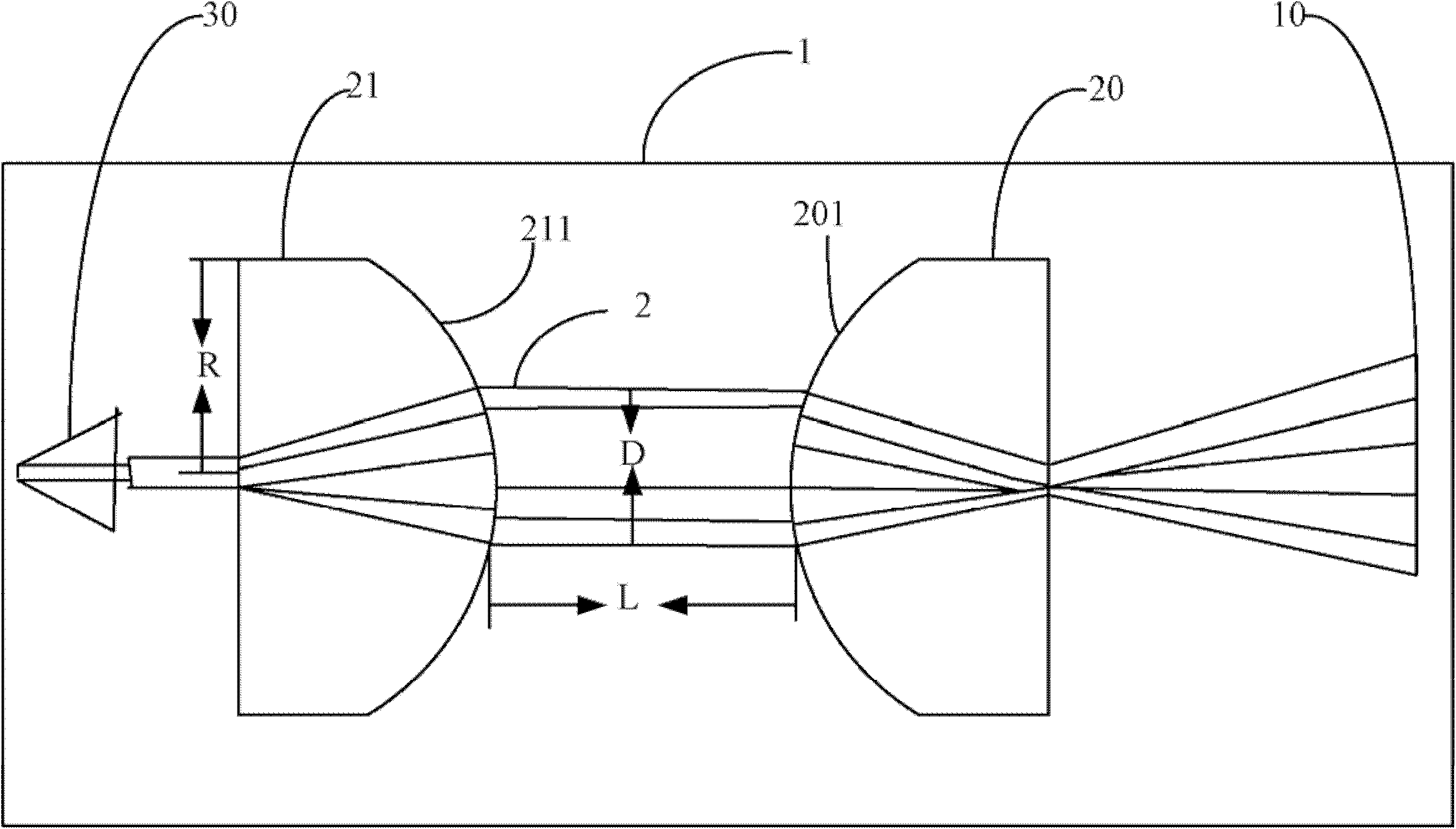
[0013] Please refer to figure 1 As shown, the fiber coupling connector 1 includes a receiving end 10 , two lenses 20 , 21 , and an insertion end 30 . The receiving end 10 is used to receive the transmitted electrical signal, convert the electrical signal into an optical signal, and transmit it to the lenses 20 and 21 through the optical fiber 2 . The lenses 20 and 21 are used to couple the optical signals transmitted through the optical fiber 2 , and transmit the coupled optical signals to the insertion end 30 . The insertion end 30 is used for converting the optical signal into an electrical signal, and inserting into the corresponding interface under the operation of the user. In this embodiment, the lenses 20 and 21 are convex aspherical mirrors, and the convex surfaces 201 and 211 of the two lenses 20 and 21 are disposed opposite to each other.

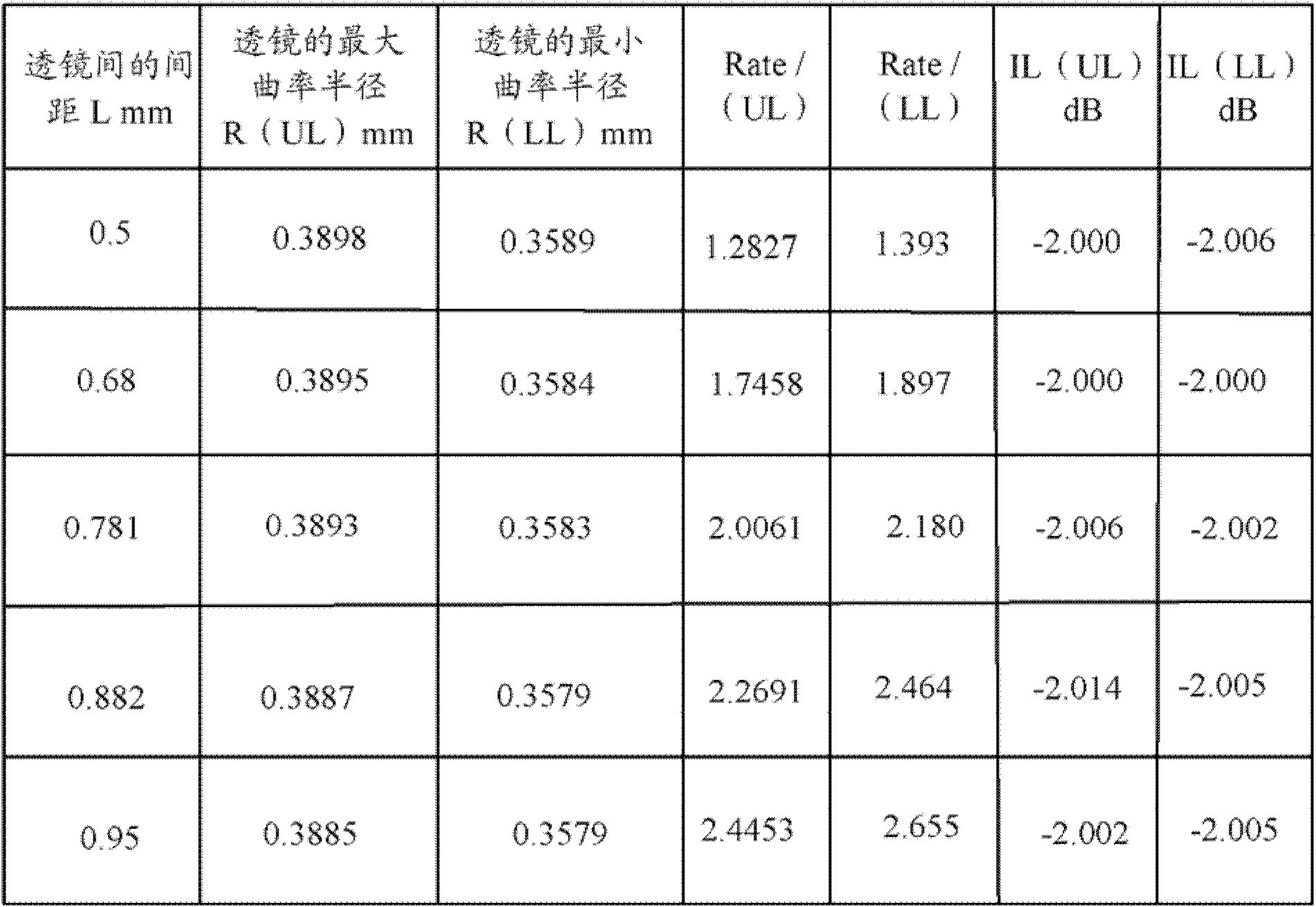
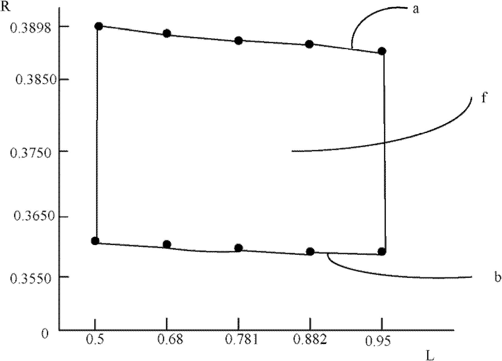
[0014] Please refer to figure 2 Shown is the experimental data table of the distance between the lenses 20, 21 in the optica...


PUM


Abstract

The invention provides an optical fiber coupled connector which comprises two lenses for coupling optical signals transmitted by an optical fiber, wherein the diameter of the optical fiber is 62.5-100 microns, the distance between the two lenses is 0.5-0.95 mm, and the curvature radiuses of the two lenses are 0.3579-0.3898 mm. By using the optical fiber coupled connector provided by the invention, the value of insertion loss can not be more than -2 dB, thereby improving the efficiency of data transmission.

Description

technical field [0001] The present invention relates to an optical fiber coupling connector. Background technique [0002] Existing fiber-coupled connectors use photoelectric conversion to convert electrical signals into optical signals, transmit the optical signals to the fiber-coupled connector for coupling, and finally re-convert the optical signal to the plug end of the fiber-coupled connector. electrical signal, and plug it into the corresponding interface. [0003] Of course, in general, when the optical signal is coupled through the lens, some insertion loss will be caused to the energy transmitted by the optical signal, and when the distance between the multiple lenses coupling the optical signal is not the same as the curvature radius of each lens itself. When matched, the value of the insertion loss will increase, thereby affecting the efficiency of the data transmitted by the optical signal. SUMMARY OF THE INVENTION [0004] The main purpose of the present inv...

Claims


Application Information

Patent Timeline
Patent Type & Authority Applications(China)
IPC IPC(8): G02B6/32G02B3/02
CPCG02B6/32
Inventor 林奕村
Owner HONG FU JIN PRECISION IND (SHENZHEN) CO LTD
Learn More