
Remote medical system

A telemedicine and functional unit technology, applied in the field of sensors, can solve problems such as overcurrent, low fault isolation, affecting sensor sensitivity, etc. Effect

Inactive Publication Date: 2011-11-23
高小勇
View PDF5 Cites 10 Cited by
  • Summary
  • Abstract
  • Description
  • Claims
  • Application Information

AI Technical Summary

Problems solved by technology

[0007] However, in the existing comprehensive telemedicine systems, various physiological parameter sensors, cameras, microphones, headsets and other external information collection devices are directly and simply connected according to their respective specifications. Sensors that use bioelectricity, pressure or temperature, such as blood pressure, ECG, and body temperature sensors, and biochemical detection sensors such as blood sugar, blood routine, urine routine, liver function, and two-and-a-half such sensors need to be detected by drugs or test strips. There are strict hygienic inspection standards for such testing instruments, which lead to different sizes of devices at the field terminals of the comprehensive telemedicine system, complex material management, difficulty in large-scale procurement and production, and inconvenient space arrangements for hardware upgrades , if there is a problem with the on-site terminal of the system, replacement parts of various specifications must be prepared during maintenance and troubleshooting, which is inconvenient for maintenance
At the same time, the fault isolation degree of the existing technology is not high. Various sensors and other functional modules are often integrated into the same circuit. If a module fails, the entire circuit has to be replaced; different modules are usually powered by the same power module. From the power terminal to the ground terminal, because the resistance of each module is different, when the field terminal encounters a thunderstorm and the mains line voltage is too high, the module with the smallest resistance will easily form an overcurrent and cause damage to the power module. Other intact modules will also fail to work; there is electromagnetic interference between the peripheral circuits of each medical sensor, which seriously affects the sensitivity of each sensor

Method used


Image

  • Remote medical system
  • Remote medical system
  • Remote medical system

Examples


Embodiment Construction

[0030] All features disclosed in this specification, or steps in all methods or processes disclosed, may be combined in any manner, except for mutually exclusive features and / or steps.

[0031] Any feature disclosed in this specification (including any appended claims, abstract and drawings), unless expressly stated otherwise, may be replaced by alternative features which are equivalent or serve a similar purpose. That is, unless expressly stated otherwise, each feature is one example only of a series of equivalent or similar features. The description of alternative solutions in this manual is a description of equivalent technical features and shall not be regarded as a contribution to the public.

[0032]If the terms used in this specification (including any claims, abstracts and drawings) have both the ordinary meaning and the specific meaning in this field, unless otherwise specified, they are all defined as the specific meaning in this field.

[0033] Such as figure 1 As...


PUM


Abstract

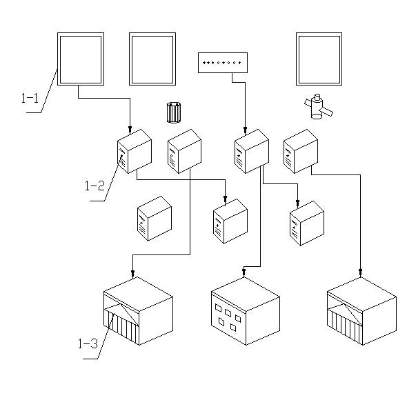
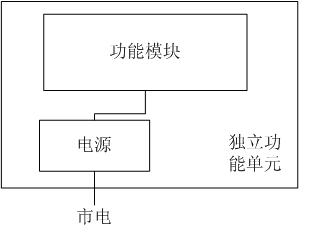
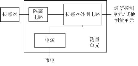
The invention discloses a remote medical system, which comprises a health cabin for detecting physiological parameters and information intersection of human bodies in site, a server for data storage and data calculation and back-end application for remote diagnosis, wherein in the health cabin, various functional modules are encapsulated by a hardware frame with an electromagnetic shielding function to form independent function units of uniform specifications; each independent function unit is provided with a power supply which is connected with a mains supply; a sensor and a peripheral circuit of the sensor are subjected to electric isolation by an isolation circuit; and a measuring unit is connected with a communication control unit in a self-healing ring mode.

Description

technical field [0001] The invention relates to the field of sensor technology and the field of medical technology, in particular to a system for performing telemedicine to users by using a variety of sensors for detecting human physiological parameters and a remote audio-visual system. Background technique [0002] The shortage of high-quality medical resources and the information asymmetry between doctors and patients have caused "difficult and expensive medical treatment" in China, which has been a long-standing problem. On the one hand, people seldom go to the hospital due to busy work or fear of hospitals, thus lacking daily monitoring of their health; institutions, resulting in the shortage of high-quality medical resources and the idleness of general medical resources. At the same time, because ordinary people often do not know much about medical information such as physiological parameters used for medical treatment, and the relationship between the medical syst...

Claims


Application Information

Patent Timeline
Patent Type & Authority Applications(China)
IPC IPC(8): G06F19/00A61B5/00A61B5/0205
Inventor 高小勇
Owner 高小勇
Learn More