
Multi-tubular fluid transfer conduit

一种流体传输、导管的技术,应用在管子/管接头/管件、管子、管元件等方向,能够解决温度和压力上升、不能燃料提供发动机制造商热保护等问题

Active Publication Date: 2011-11-23
WOODWARD GOVERNOR CO
View PDF5 Cites 13 Cited by
  • Summary
  • Abstract
  • Description
  • Claims
  • Application Information

AI Technical Summary

Problems solved by technology

However, the evolution of gas turbines is such that the temperature and pressure of the compressor discharge air rises considerably so that thermal protection of the fuel becomes even more than a design challenge
For many applications, it has been found that a conventional single insulated fuel gap filled with an air-fuel-coke mixture does not provide adequate thermal protection of the fuel as required by engine manufacturers

Method used


Image

  • Multi-tubular fluid transfer conduit
  • Multi-tubular fluid transfer conduit
  • Multi-tubular fluid transfer conduit

Examples


Embodiment Construction

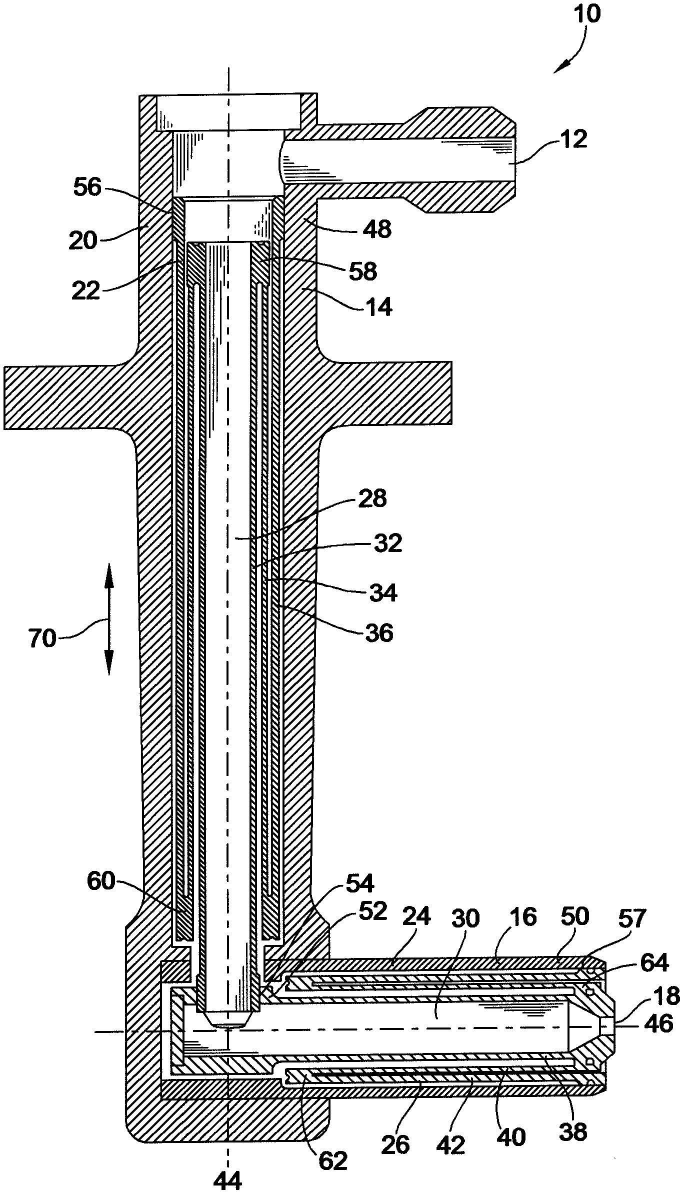
[0034] figure 1 A cross-sectional view of a fuel nozzle 10 including a fuel delivery duct 22 according to an embodiment of the present invention is shown. The fuel nozzle 10 may be implemented in a gas turbine system to inject fuel into a combustion chamber, where the fuel is mixed with air and burned at a high temperature while maintaining close to static pressure. The gas temperature required in the turbine varies according to the engine speed, so the combustion chamber must be capable of stable and effective combustion in a wide range of operating conditions, which can be maintained for an extended period of time. The temperature of the air leaving the main combustion zone can be about 1800°C and 2000°C. The fuel nozzle 10 includes an improved fuel delivery conduit 22, which can better receive structural stress caused by heat and better protect the fuel against the severe temperatures of the gas turbine system.

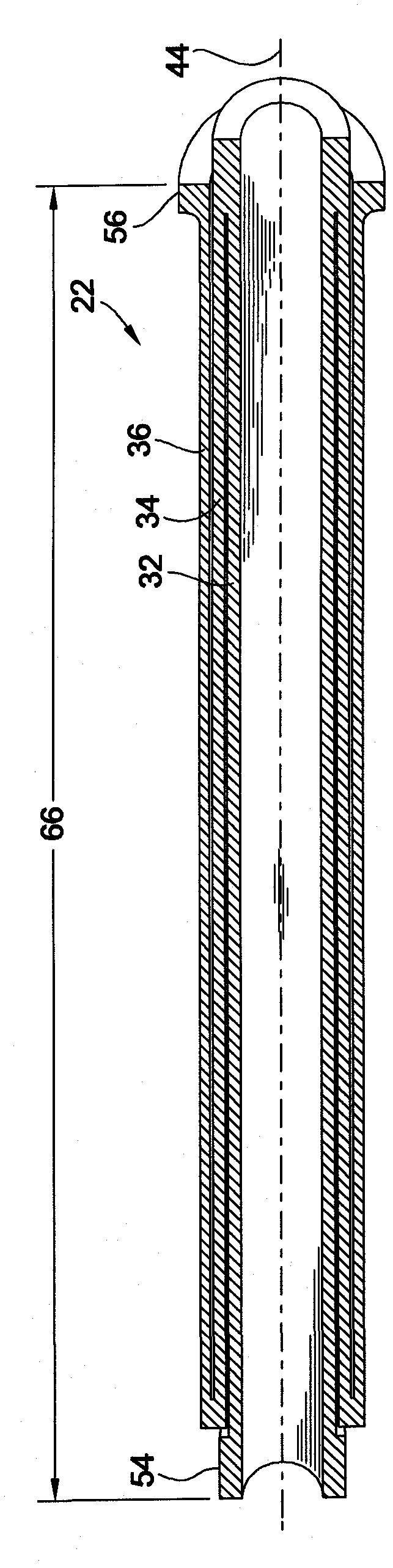
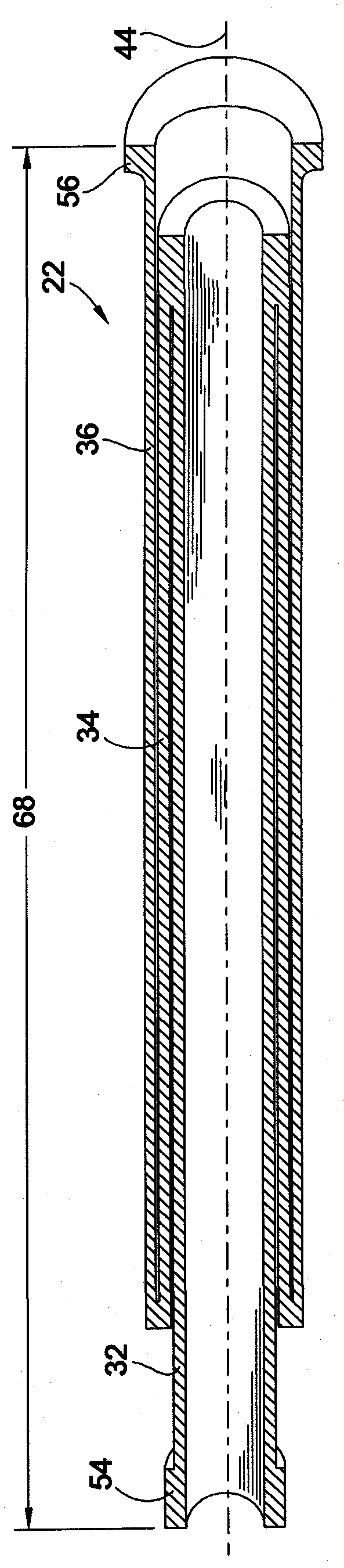
[0035] Although the fuel delivery duct 22 in this embodiment is...


PUM


Abstract

A fluid transfer system having improved stress accommodation properties and thermal insulation properties is provided. The fluid transfer system includes a fluid transfer conduit comprising a plurality of concentric tubes configured to divide and distribute an axial stress induced in the fluid transfer conduit to each of the tubes and a vacuum cavity between the fluid transfer conduit and a structural support of the fluid transfer system to insulate fluid from a surrounding environment.

Description

Technical field [0001] The present invention relates generally to a fluid transfer device, and more particularly to a fluid transfer conduit configured for effective thermal insulation and receiving structural stress. Background technique [0002] Generally, fluid transfer devices, such as tubular conduits, are subject to mechanical stress, such as thermal expansion due to external forces. In the tubular duct structure, the tensile force along the tube axis caused by thermal expansion at the end of the tubular duct generates tensile stress in the duct structure, while the thrust generates compressive stress. Generally, excessive such stress causes structural failure of the catheter. In addition, in certain applications, heat transfer between the fluid flowing through the conduit and the surrounding environment may be problematic. For example, it has become a challenge to insulate the steam pipe to reduce the heat loss of the steam as it flows through the duct. [0003] Fluid tra...

Claims


Application Information

Patent Timeline
Patent Type & Authority Applications(China)
IPC IPC(8): F16L9/18F02M61/18F16L9/19F16L59/06
CPCF23D14/78F16L59/21F23R3/00F23R3/283F16L51/00F23D14/76F16L9/19F16L9/18
Inventor F·P·李R·J·沃辛顿
Owner WOODWARD GOVERNOR CO
Learn More