
Sputtering carrier

A carrier and sputtering technology, which is applied in the field of carriers, can solve the problems of difficult cleaning and high cost, and achieve the effects of no static residue, low manufacturing cost and small deformation

Inactive Publication Date: 2011-11-30
HONG FU JIN PRECISION IND (SHENZHEN) CO LTD +1
View PDF4 Cites 2 Cited by
  • Summary
  • Abstract
  • Description
  • Claims
  • Application Information

AI Technical Summary

Problems solved by technology

The tray made of metal is not easy to deform, but the cost is high, and it is difficult to clean

Method used


Image

  • Sputtering carrier
  • Sputtering carrier
  • Sputtering carrier

Examples


Embodiment Construction

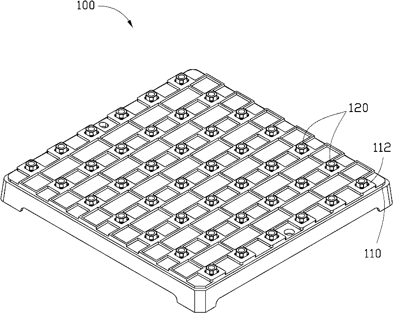
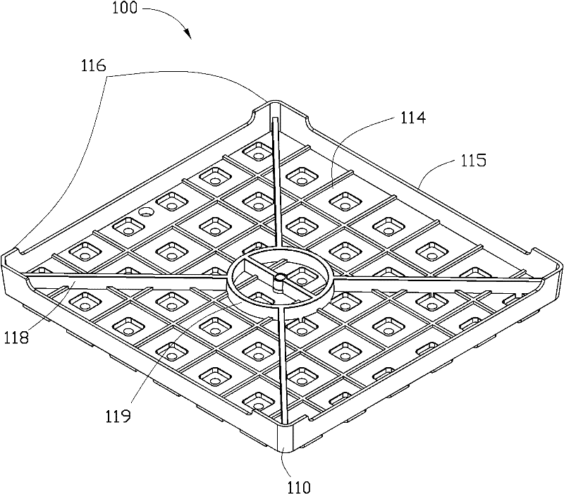
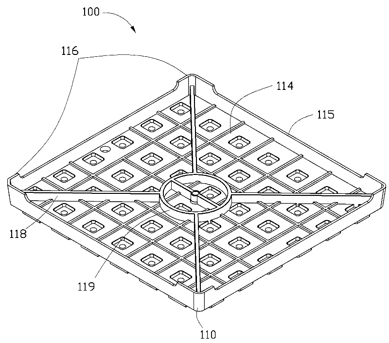
[0018] see figure 1 , a sputtering carrier 100 provided by a preferred embodiment of the present invention includes a base 110 and a plurality of support bases 120 arranged in an array on one side of the base 110 . The base 110 is rectangular and includes an upper surface 112 and a lower surface 114 opposite to the upper surface 112 . The supporting bases 120 are evenly spaced on the upper surface 112 of the base 110 . A supporting wall 115 extends around the lower surface 114 of the base 110 . Four corners of the supporting wall 115 respectively extend a leg 116 along a direction perpendicular to the lower surface. A reinforcing rib 118 extends from the inner side of each leg 116 toward the center of the base 110 . The plurality of reinforcing ribs 118 intersect on an annular wall 119 at the center of the lower surface 114 of the base 110 .

[0019] The sputtering carrier 100 is made by melt-blending polycarbonate and glass fiber and molding. Specifically, polycarbonate ...


PUM

PropertyMeasurementUnit
diameteraaaaaaaaaa
lengthaaaaaaaaaa
lengthaaaaaaaaaa

Abstract

The invention relates to a sputtering carrier, which comprises a base and a plurality of supporting bases arranged in an array on the base. The sputtering carrier is molded by melting and blending polycarbonate and glass fiber with a mass ratio of 9:1. The sputtering carrier of the present invention is molded by mixing polycarbonate and glass fiber, so it has good heat resistance, small deformation, no static residue, easy processing and low manufacturing cost.

Description

technical field [0001] The invention relates to a carrier, in particular to a sputtering carrier applied in a sputtering process. Background technique [0002] During the sputtering process, in order to improve production efficiency, usually multiple workpieces to be coated are loaded on a tray at the same time, and then the tray together with the workpieces to be coated on it are sent into the coating device for sputtering. Due to the high environmental requirements in the sputtering process, the physical characteristics of the tray itself are also very demanding, for example, the tray needs to be resistant to high temperatures and has a small deformation rate. Traditional trays are usually made of plastic or metal. Trays made of plastic are less expensive but easily deformed. And the pallet made of metal is not easy to deform, but the cost is high, and it is difficult to clean. Contents of the invention [0003] In view of this, it is necessary to provide a low-cost a...

Claims


Application Information

Patent Timeline
Patent Type & Authority Applications(China)
IPC IPC(8): C23C14/34
Inventor 林后尧裴绍凯
Owner HONG FU JIN PRECISION IND (SHENZHEN) CO LTD
Learn More