Separate rotary valve assembly for changing air direction of regenerative combustion device and regenerative combustion system including the same

A technology of combustion device and wind direction conversion, applied in combustion method, combustion type, lighting and heating equipment, etc., can solve problems such as mixing and reduction of gas flow efficiency

Inactive Publication Date: 2011-11-30
ACE TECH
View PDF6 Cites 20 Cited by
  • Summary
  • Abstract
  • Description
  • Claims
  • Application Information

AI Technical Summary

Problems solved by technology

[0018] That is, in the FCDPR SEAL which is in contact with the separation chamber cylinder and the exhaust chamber cylinder and is sealed, when the circular FCDPR SEAL is installed without forming a perfect circle, there will be a gap between the cylinder and the cylinder. When the rotary valve is rotated, there may be a problem of mixing a small amount of supply gas and exhaust gas between the upper and lower directions with the FCDPR SEAL as the reference. In addition, the CR SEAL installed in the vertical direction to the separation chamber cylinder In this case, when rotating, a gap is generated between the upper surface and the lower surface of the CR SEAL, so that there may be a structural problem that a trace amount of supply gas and exhaust gas are mixed between adjacent space parts in the horizontal direction, and at the same time , because the surrounding part of one side end of the rotary valve is opened and formed, and the passages of the supply gas, exhaust gas and clean gas communicated with the separation chamber are formed in the lateral direction through the equal-spaced partitions arranged at equal intervals in the open surrounding part, As a result, the direction of vertical travel of the gas flow flowing from bottom to top or from top to bottom is unnecessarily changed, and there is a problem that the gas flow efficiency is reduced

Method used


Image

  • Separate rotary valve assembly for changing air direction of regenerative combustion device and regenerative combustion system including the same
  • Separate rotary valve assembly for changing air direction of regenerative combustion device and regenerative combustion system including the same
  • Separate rotary valve assembly for changing air direction of regenerative combustion device and regenerative combustion system including the same

Examples


Embodiment Construction

[0050] Hereinafter, preferred embodiments of the present invention will be described in detail with reference to the accompanying drawings.

[0051] First, refer to the Figure 4 to Figure 16 Basic structural diagram and detailed structural diagram of the present invention of the preferred embodiment shown, and as Figure 17 to Figure 31 The operational state diagrams and other embodiments shown illustrate the preferred embodiments of the present invention.

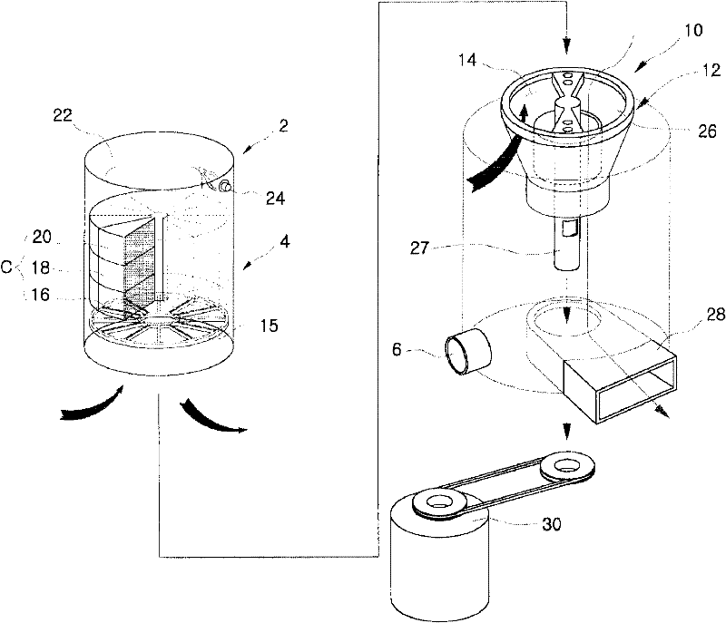
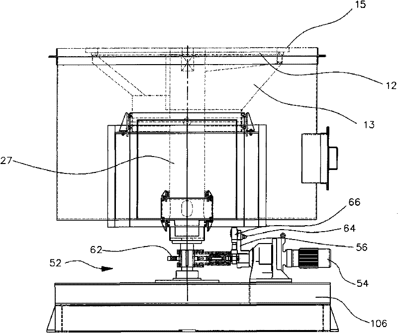
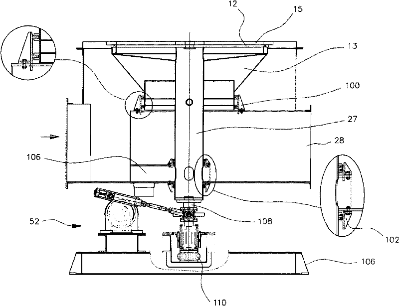
[0052] see Figure 4 to Figure 8 , the regenerative combustion system using the wind direction conversion device for the regenerative combustion device according to the present invention has the following structure as a whole, between the regenerative combustion device 100 and the gas pipeline part 400, there is a A circular dome-shaped distribution chamber 200 and a rotor 300 of the wind direction converter. Among them, the above-mentioned regenerative combustion device 100 includes: an incineration chamber 110 for in...


PUM


Abstract

The invention provides a separable rotary valve assembly for shifting wind of a heat accumulating burning device, which configure an upper portion rotating distributing board of a rotor of the separable rotary valve assembly detachably installed on the heat accumulating burning device and disposed in a wind shifting device to a be hollow circular disc, particularly, clean gas injecting holes are disposed along the circumferential direction of the upper portion rotating distributing board to supply clean gas along the whole circumferential direction of the upper portion rotating distributing board, and a clean gas supply channel is disposed along the upper surface of a rotating gas distributing chamber at the lower part of the upper portion rotating distributing board, a fine gap within a set range disposed between the upper portion rotating distributing board and a lower portion fixed distributing board of the distributing chamber fixedly disposed on the upper portion rotating distributing board is kept to prevent friction loss, and a gas curtain is formed via the fine gap ejecting the clean gas, thereby providing a cooling function of absorbing high heat, also, a gap fine adjusting device is additionally added at the lower portion of the rotor to adjust the above fine gap.

Description

technical field [0001] The present invention relates to a separate rotary valve assembly for wind direction conversion of a regenerative combustion device, in particular to a rotary valve assembly that can be attached and detached to a regenerative combustion device as a separate wind direction conversion device. When the rotor of the rotary valve assembly rotates, it prevents leakage between the lower fixed distribution plate of the fixed distribution chamber and the upper rotating distribution plate of the rotor, resulting in untreated supply gas and treated exhaust gas. The mixing phenomenon that occurs between, at the same time, provide cleaning devices and gap adjustment devices to minimize frictional damage between the upper rotating distribution plate of the rotor and the lower fixed distribution plate of the distribution chamber, as well as thermal deformation caused by high temperature Phenomenon. Background technique [0002] The present invention relates to a vol...

Claims


Application Information

Patent Timeline
Patent Type & Authority Applications(China)
IPC IPC(8): F23G7/06
CPCY02E20/34
Inventor 宋哲焕
Owner ACE TECH
Why Eureka
Try Eureka