A Method for Measuring Near-field Light Intensity Distribution Using the Arrangement Shape of Nanoparticles

A nanoparticle and near-field light technology, applied in the field of near-field optics and nano-operations, can solve problems such as cost increase and process complexity, and achieve the effects of low cost, simple structure, and improved research capabilities

Inactive Publication Date: 2011-11-30
HARBIN INST OF TECH
View PDF0 Cites 6 Cited by
  • Summary
  • Abstract
  • Description
  • Claims
  • Application Information

AI Technical Summary

Problems solved by technology

If the near-field distribution of the total reflection interface and the nano-aperture is directly studied through the tip of the fiber optic probe, the operation is not only complicated but also the cost is greatly increased. Approximate model, through the study of the model to understand the nature of the near-field light intensity distribution

Method used


Image

  • A Method for Measuring Near-field Light Intensity Distribution Using the Arrangement Shape of Nanoparticles
  • A Method for Measuring Near-field Light Intensity Distribution Using the Arrangement Shape of Nanoparticles
  • A Method for Measuring Near-field Light Intensity Distribution Using the Arrangement Shape of Nanoparticles

Examples


Embodiment 1

[0050] Embodiment 1: The detection of near-field distribution is realized by adopting the method of capturing nanoparticles to form an arrangement shape with an optical fiber probe.

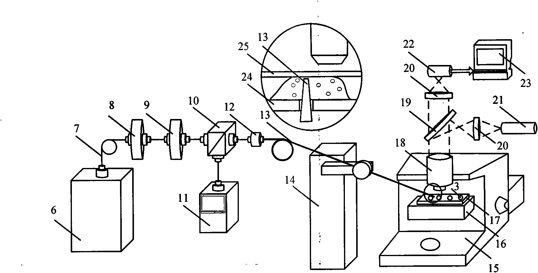
[0051] The structure diagram of the method is as follows image 3 shown, combined with image 3 The specific steps of the near-field detection method are described in detail as follows:

[0052] After the semiconductor laser 6 is output by the polarization-maintaining pigtail 7, the flange adjustable optical attenuator 8 is added, and the power is adjusted by adjusting the driving source current and the power attenuator 8, and then the polarization direction is adjusted through the optical fiber polarization rotator 9, and then the optical fiber is split One beam of laser light is distributed from the device 10 to the fiber optic power meter 11 for power monitoring, and the other beam is connected to the single-mode near-field fiber optic probe 13 through the fiber optic adapter 12 . Considerin...

Embodiment 2

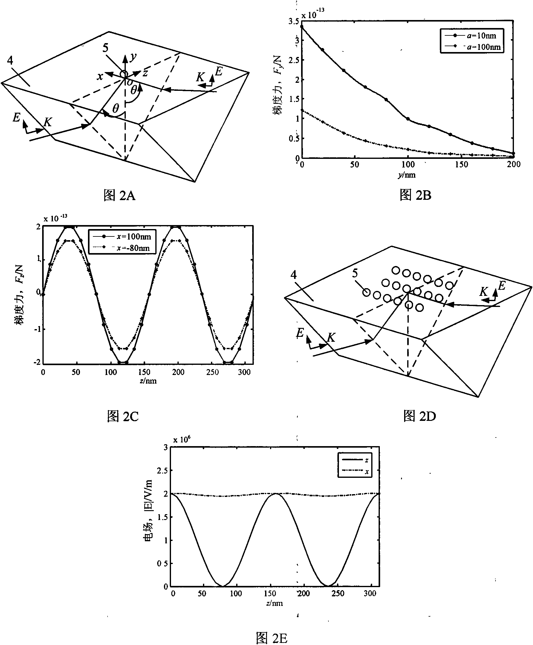
[0053] Embodiment 2: The detection of near-field distribution is realized by using the method of trapping nanoparticles in the coherent evanescent field of prism total internal reflection.

[0054] The structure of the method Figure 4 shown, combined with Figure 4 The specific steps of coherent evanescent field detection are described in detail as follows:

[0055]First, the diluted polystyrene bead 5 solution is adsorbed onto the surface of the prism 4, and a cover glass 25 is placed on top, and then the density and dispersion of the upper surface of the prism 4 are roughly selected using the coarse adjustment system of the laser scanning confocal microscope 15. Then, the micro-feeding system is used to bring the focal plane close to the polystyrene bead 5 to precisely position the single-layer nanoparticles. The linearly polarized laser beam emitted by the laser 26 passes through the beam expander lens group 27 and enters the half-wave plate 28 to adjust the polarization...


PUM


Abstract

The invention discloses a method for measuring near-field light intensity distribution by utilizing the arrangement shape of nano particles. It is a method that uses the strong gradient force generated by the evanescent field to operate nanoparticles, and detects the near-field light intensity distribution according to the arrangement pattern generated after the operation. After the nanoparticles are placed in the near-field region of the fine structure, the rapidly decaying evanescent field can provide the gradient force required to capture the particles, so as to realize the stable and efficient capture operation of the nanoparticles. The three-dimensional optical trap formed in the near-field region can balance the external interference force, and stably capture and confine the nanoparticles near the light intensity pole. Therefore, the pattern shape formed by the final arrangement of the particles can reflect the light intensity distribution in the fine-structure near-field region. Utilizing the arrangement shape of nanoparticles in the near-field region, the precise detection of near-field light intensity on fine-structured surfaces can be realized.

Description

technical field [0001] The invention belongs to the field of near-field optics and nanometer operation, in particular to a method for measuring near-field light intensity distribution by using the arrangement shape of nano particles. Background technique [0002] With the advancement of science and technology to small-scale and low-dimensional spaces, a new interdisciplinary subject, near-field optics, has emerged in the field of optics. Near-field optics has revolutionized the traditional optical resolution limit. The light field on the surface of an object contains two components. One is the propagation field that is generated by the rough structure of the object and can propagate far away. The formed far field contains only propagating waves, including only the low spatial frequency part of the electromagnetic field, and does not contain the sample. The subwavelength structural information of the object; the other is the non-radiative evanescent field that is localized on...

Claims


Application Information

Patent Timeline
Patent Type & Authority Applications(China)
IPC IPC(8): G01J1/58
Inventor 杨立军刘炳辉王扬
Owner HARBIN INST OF TECH
Why Eureka
Try Eureka