
Manufacturing method of multicolour dimming mask and pattern transfer method

A manufacturing method and photomask technology, which are applied in the photoengraving process of the pattern surface, the original for photomechanical processing, and the manufacture of semiconductor/solid-state devices, etc., can solve the problem of uneven film reduction speed and difficulty in film reduction. Problems such as shape control and reduction of transfer pattern formation accuracy, to achieve the effect of improving in-plane uniformity and formation accuracy

Active Publication Date: 2013-10-16
HOYA CORP
View PDF2 Cites 1 Cited by
  • Summary
  • Abstract
  • Description
  • Claims
  • Application Information

AI Technical Summary

Problems solved by technology

As a result, it is difficult to accurately control the shape of the subtractive film, which sometimes leads to a decrease in the formation accuracy of the transfer pattern
Especially in photomasks for FPDs, the density difference of the resist pattern is large, so there is a tendency that the film-reducing speed is uneven

Method used


Image

  • Manufacturing method of multicolour dimming mask and pattern transfer method
  • Manufacturing method of multicolour dimming mask and pattern transfer method
  • Manufacturing method of multicolour dimming mask and pattern transfer method

Examples


no. 1 Embodiment approach

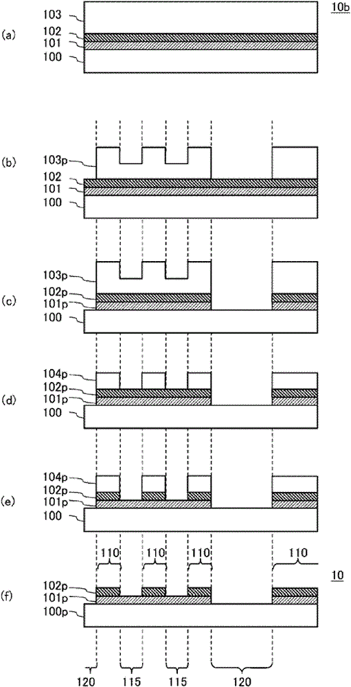
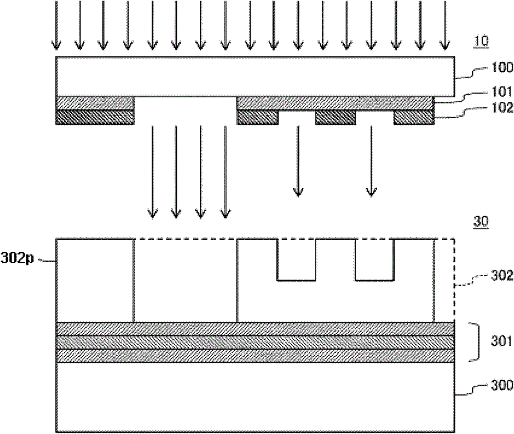
[0053] Below, refer to figure 1 with figure 2 The first embodiment of the present invention will be described. figure 1 It is a flowchart of the manufacturing process of the multi-color photomask 10 of this 1st Embodiment. figure 2 It is a cross-sectional view showing a pattern transfer method using the multi-color photomask 10 .

[0054] (1) Manufacturing method of multi-color photomask

[0055] (Photomask blank preparation process)

[0056] First, if figure 1 As shown in (a) 1, prepare a photomask blank 10b in which a light semitransmissive film 101 and a light shielding film 102 are sequentially formed on a transparent substrate 100, and a resist film 102 is formed on the uppermost layer. etchant film 103.

[0057] The transparent substrate 100 is, for example, constituted as a flat plate made of quartz (SiO 2 ) glass, or containing SiO 2 、Al 2 o 3 , B 2 o 3 , RO (R is an alkaline earth metal), R 2 O(R 2 It is composed of low-expansion glass such as alkali m...

no. 2 Embodiment approach

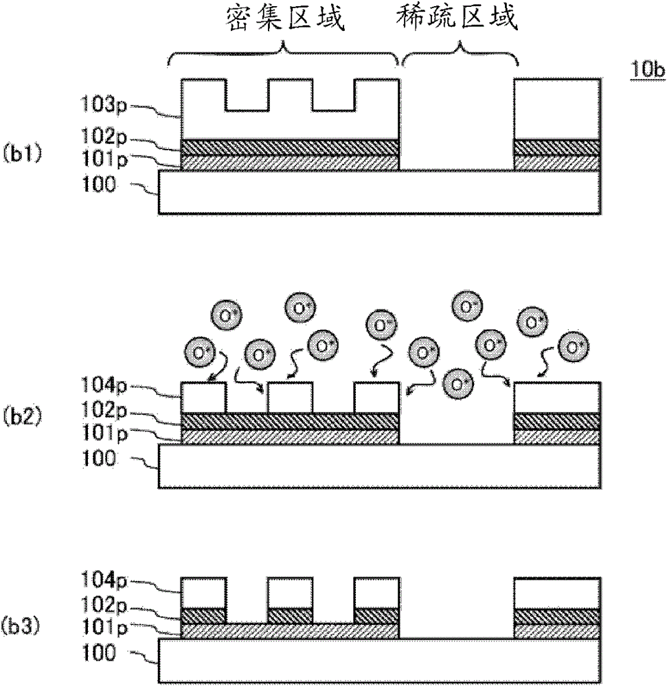
[0099] Next, a second embodiment of the present invention will be described. In this second embodiment, oxygen or ozone gas can be used instead of ozone water, and light irradiation can be performed in an environment where the oxygen or ozone gas exists, thereby achieving a state of excess supply of gaseous ozone or active oxygen containing ozone. Thus, the difference from the first embodiment described above is that generation of active oxygen is promoted, thereby performing film reduction on the first resist pattern 103p. Below, refer to figure 1 Differences from the first embodiment described above will be described in detail.

[0100] The method of manufacturing the multi-color photomask 10 of the second embodiment is also the same as that of the above-mentioned first embodiment. figure 1 The manufacturing process illustrated is, however, carried out by light irradiation while supplying ozone gas in the manufacturing method of the multi-color photomask 10 of the second e...


PUM


Abstract

PROBLEM TO BE SOLVED: To reduce the number of drawing and developing processes by using film reduction of a resist pattern, as well as to improve uniformity within a film plane in a film reduction rate of a resist pattern between sparse and dense pattern regions.SOLUTION: A method for manufacturing a photomask is provided, including steps of: forming a first resist pattern covering a region for forming a light-shielding portion and a region for forming a translucent portion, in which the thickness of the resist film in the region for forming a translucent portion is smaller than the thickness of the resist film in the region for forming a light-shielding portion; and reducing the film in the first resist pattern by excessively supplying ozone to the first resist pattern. Ozone is supplied in such a manner that the supply amount of active oxygen per unit area supplied to the first resist pattern is greater than the consumed amount of active oxygen per unit area consumed by the film reduction in the first resist pattern.

Description

technical field [0001] The present invention relates to a method of manufacturing a multi-color photomask used in the manufacture of a flat panel display (Flat Panel Display: hereinafter referred to as FPD) such as a liquid crystal display device, etc., and a method of pattern transfer using the multi-color photomask . Background technique [0002] For example, a thin film transistor (Thin Film Transistor: hereinafter referred to as TFT) substrate for FPD uses a photomask in which a transfer pattern consisting of a light-shielding portion and a light-transmitting portion is formed on a transparent substrate. produced by photolithography process. In recent years, in order to reduce the number of photolithography steps, a multi-color photomask in which a transfer pattern including a light-shielding portion, a semi-transmitting portion, and a light-transmitting portion is formed on a transparent substrate has been used. [0003] In the above-mentioned multi-color light mask, ...

Claims


Application Information

Patent Timeline
Patent Type & Authority Patents(China)
IPC IPC(8): G03F1/32G03F7/20G03F7/00G03F1/00G03F1/68G03F1/80
CPCG03F1/58G03F1/66H01L21/0275H01L21/0337
Inventor 长岛奖
Owner HOYA CORP
Learn More