In situ force and electrical performance comprehensive test sample rod with biaxial tilting for transmission electron microscope

A technology of biaxial tilting and transmission electron microscopy, which is applied in the direction of applying stable tension/pressure to test the strength of materials, components of electrical measuring instruments, circuits, etc., which can solve the dynamic research of in-situ deformation that cannot be achieved without tilting , Unable to achieve stress loading and other problems, to achieve the effect of shortening the length

Active Publication Date: 2011-11-30
BESTRONST (BEIJING) SCI & TECH CO LTD
View PDF7 Cites 59 Cited by
  • Summary
  • Abstract
  • Description
  • Claims
  • Application Information

AI Technical Summary

Problems solved by technology

Although the above-mentioned commercial TEM deformation device provides a favorable tool for in situ research on the microstructure changes during the deformation process of nanomaterials, there is a technical bottleneck obstacle: the in situ mechanical behavior of the commercial TEM sample stretching table is basically Single-axis tilting, unable to achieve tilting along the Y-axis
In addition, although the commercial dual-axis tilting sample holder technology is very mature, these sample holders can only realize the observation of the sample but cannot realize the stress loading on the sample in the sample plane under the condition of dual-axis tilting, which limits the researcher. In-situ study of deformation, fracture, phase transition and other mechanisms of materials at the atomic scale
[0004] It should be pointed out that the above methods are mai

Method used


Image

  • In situ force and electrical performance comprehensive test sample rod with biaxial tilting for transmission electron microscope
  • In situ force and electrical performance comprehensive test sample rod with biaxial tilting for transmission electron microscope
  • In situ force and electrical performance comprehensive test sample rod with biaxial tilting for transmission electron microscope

Examples


Embodiment Construction

[0033] The present invention will be described in further detail below in conjunction with the accompanying drawings.

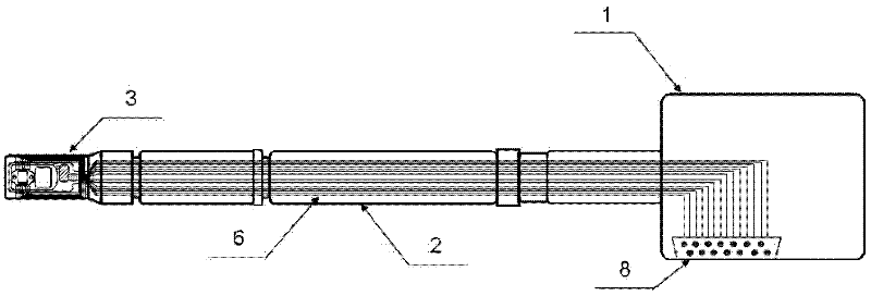
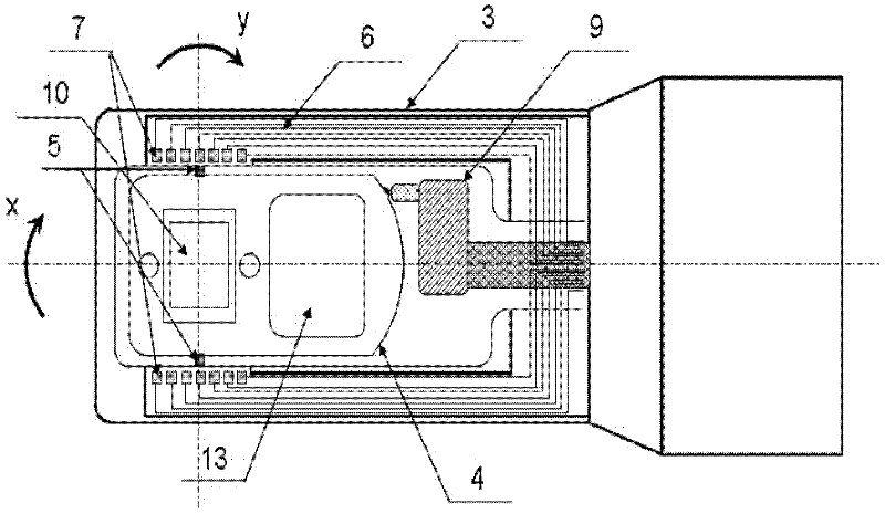
[0034] Such as figure 1 , as shown in 2, the in-situ force and electrical performance comprehensive test sample rod with biaxial tilting for transmission electron microscopy mainly includes a handle 1, a sample rod 2, a front end 3 of the sample head, and a sensor carrier 4 passes through the front end 3 of the sample head. The two inner support shafts 5 are fixed on the front end 3 of the sample head, tilt around the support shaft 5 in a plane perpendicular to the sample head (that is, rotate around the Y axis, ±30°), and the walls on both sides of the front end 3 of the sample head On the top, the wires I 6 introduced from the outside of the electron microscope through the sample rod 2 are symmetrically distributed, and are connected to the queue electrodes I 7 distributed on the two side walls of the front end 3 of the sample head, and the other end of th...


PUM


Abstract

The invention relates to a comprehensive test sample rod for double-shaft tilting in-situ force and electric property of a transmission electron microscope, belonging to the researching field of in-situ measurement of transmission electron microscope accessories and nanometer materials. The comprehensive test sample rod comprises a self-designed transmission electron microscope sample rod, a force/electric property sensor, a pressing sheet, a front end of sample rod and a sensor carrier, wherein the force/electric property sensor is fixed on the sensor carrier at the front end of sample rod through the pressing sheet; the sensor carrier is connected to the front end of sample rod through rotating shafts located on two sides and can rotate around the two rotating shafts in a plane verticalto the front end of sample rod (namely rotating for +/-30 degrees around Y shafts); and electrodes of the force/electric property sensor are connected to the electrodes on the two sides of the front end of the sample rod through the pressing sheet and are connected to an external test device through leads in the sample rod, thereby realizing the in-plane loading (in a sensor plane) of a force/electric signal and the feedback real-time monitoring. The comprehensive test sample rod can be used for tilting a searching sample to be under a low-index positive belt shaft, thereby realizing in-situ atomic scale observation while acquiring force/electric comprehensive property parameters.

Description

Technical field: [0001] The invention relates to a comprehensive performance testing sample rod for a transmission electron microscope. The sample rod realizes the comprehensive performance of the material while realizing the loading of the stress in the plane where the sample is located while realizing a large-angle tilt along a pair of orthogonal axes. Testing, real-time research on the in-situ dynamics of material micro-region deformation from the atomic scale. The invention belongs to the research field of transmission electron microscope accessories and in-situ measurement of nanomaterials. Background technique: [0002] Since the invention of the transmission electron microscope in the 1930s (1932), especially in the past two decades, the transmission electron microscopy technology has improved in spatial resolution represented by spherical aberration correction technology and energy resolution represented by monochromatic light source. Great progress has been made in...

Claims


Application Information

Patent Timeline
IPC IPC(8): H01J37/20G01N23/04
CPCG01N3/08G01R1/00H01J2237/2062G01N2223/307G01N2203/0286H01J2237/20207H01J37/26H01J37/20G01N23/04H01J2237/206
Inventor 韩晓东岳永海张跃飞刘攀郑坤张泽
Owner BESTRONST (BEIJING) SCI & TECH CO LTD
Why Eureka
Try Eureka