Power plant with co2 capture

A power equipment, CO2 technology, applied in the direction of mechanical equipment, engine components, engine control, etc., can solve the problems of performance, efficiency and operability, etc.

Active Publication Date: 2011-11-30
GENERAL ELECTRIC TECH GMBH
View PDF8 Cites 11 Cited by
  • Summary
  • Abstract
  • Description
  • Claims
  • Application Information

AI Technical Summary

Problems solved by technology

CO 2 This change in concentration for CO 2 potentially detrimental to the performance, efficiency, and operability of capture systems

Method used


Image

  • Power plant with co2 capture
  • Power plant with co2 capture
  • Power plant with co2 capture

Examples


Embodiment Construction

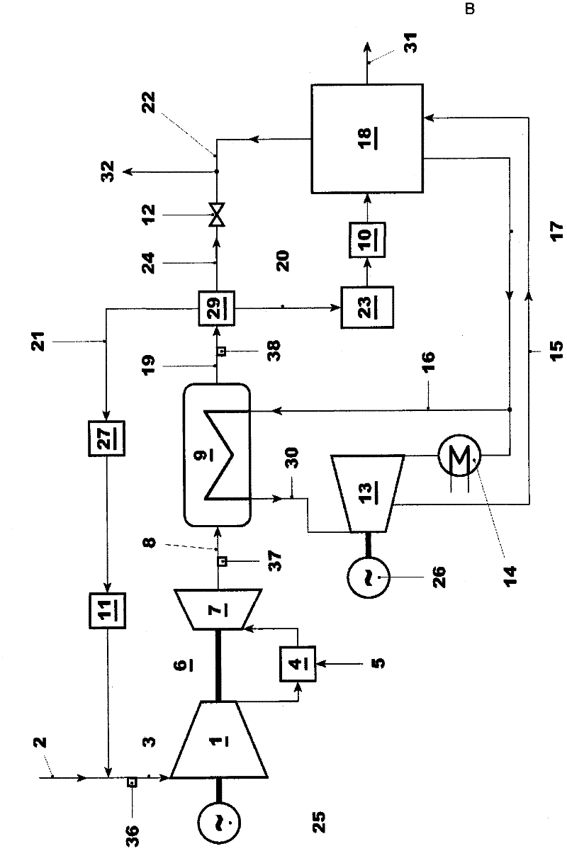
[0058] The power plants used to perform the proposed method include conventional CCPPs, equipment for flue gas recirculation and CO 2 capture system 18 .

[0059] exist figure 1 A typical arrangement with post combustion capture and flue gas recirculation is shown in . A turbine 6 driving a first generator 25 is supplied with compressor inlet gas 3 and fuel 5 . The compressor inlet gas 3 is a mixture of ambient air 2 and flue gas recirculated through the flue gas recirculation line. Inlet gas is compressed in compressor 1 . The compressed gas is used in combustor 4 to burn fuel 5 and the pressurized hot gas is expanded in turbine 7 . Its main outputs are electrical power and hot flue gas8.

[0060] The hot flue gas 8 of the gas turbine passes through the HRSG 9 , which generates live steam 30 for the steam turbine 13 . The steam turbine 13 is arranged either in a single-shaft configuration with the gas turbine 6 and the first generator 25 , or in a multi-shaft configurat...


PUM


Abstract

Since CO2 is identified as a main greenhouse gas, its capture and storage is essential to control global warming. Flexible, optimized operation of CCPPs (combined cycle power plants) with a CO2 capture system (18) will increase the competitiveness of CCPPs designed for CO2 capture and will allow earlier introduction of this kind of plants. The main objective of the present invention is to provide a method for the optimized operation of a CCPP with flue gas recirculation and CO2 capture system (18) as well as a plant designed to operate according to this method. To this end a combination of two parameters to optimize the overall plant efficiency is proposed. These are CO2 concentration in the flue gases, and the re- cooling temperature of the recirculated flue gases. Additionally it is found to be advantageous to control the flue gas flow, which is sent to the CO2 capture system (18). These parameters are given as functions over load to optimize the overall plant efficiency including the CO2 capture system (18). Besides the method a power plant designed to operate according to this method is subject of the present invention. Further, admixing of oxygen or oxygen enriched air to the gas turbine inlet gases (3) to enhance operatability is proposed.

Description

technical field [0001] The present invention relates to a system for operating an integrated CO 2 A method for a combined cycle power plant with capture and flue gas recirculation, and an apparatus for performing such a method. Background technique [0002] In recent years, it has become apparent that the production of greenhouse gases leads to global warming and that further increases in the production of greenhouse gases will accelerate global warming. Because CO 2 (Carbon dioxide) is recognized as the main greenhouse gas, so CCS (Carbon Capture and Storage) is regarded as one of the potential main means to reduce the release of greenhouse gases into the atmosphere and control global warming. In this context, CCS is defined as CO 2 The process of capturing, compressing, transporting and storing. Capture is defined as a process in which CO 2 Either removed from the flue gas after combustion of the carbon-based fuel, or by removing and treating the carbon prior to combu...

Claims


Application Information

Patent Timeline
Patent Type & Authority Applications(China)
IPC IPC(8): F01K23/10F02D21/04F02C3/34
CPCF02M25/10Y02E20/16F02C3/34F05D2260/61F02C6/003F02C6/18F01K23/101Y02E20/18B01D2257/504Y02E20/14Y02C20/40Y02E20/32
Inventor 李洪涛J·霍夫曼H·纳格尔F·德劳克斯C·马耶C·鲁赫蒂M·维尔苏姆
Owner GENERAL ELECTRIC TECH GMBH
Why Eureka
Try Eureka